Friday, January 24, 2020

Creating & Modifying Surfaces - Video Tutorial


To Record a Preview Animation

  1. Image result for To Record a Preview Animation 3d autocadIf the Animations panel is not displayed on the Visualize tab, right-click the Visualize tab and click Panels Animations.
  2. Start any navigation command such as 3DORBIT.
  3. Click Visualize tab Animations panel Animation Record.
  4. Navigate through the model to record the movement.
  5. When you are finished recording the animation, click Visualize tab Animations panel Animation Pause.
  6. To review the animation, click Visualize tab Animations panel Animation Play. In the Animation Preview dialog box, view the recording to verify that the animation is suitable for your presentation needs.
    Note:
    The playback of the animation gives you a general visual idea of the final output. It may not display the visual style or with the same quality of the final output.
  7. If you are satisfied with the animation, click the Pause button. Then click the Save button.
  8. In the Save As dialog box, choose a location and file name.
    Note:
    To change the file type, click the Animation Settings button. In the Animation Settings dialog box, Format option, click a file type. Click OK to return to the Save As dialog box.
  9. Click Save.

Creating Preview Animations


Image result for Creating Preview AnimationsYou can create 3D preview animations and adjust the settings before you create a motion path animation.
Preview animations are created with the controls on the Animation panel found on the ribbon and the 3D navigation tools. Once a 3D navigation tool is active, the controls on the Animation panel are enabled to start recording an animation.
The following commands can be used to create an animation
  • 3DCORBIT
  • 3DDISTANCE
  • 3DFLY
  • 3DFORBIT
  • 3DORBIT
  • 3DPAN
  • 3DSWIVEL
  • 3DWALK
  • 3DZOOM
To learn more about the 3D navigation tools available for creating an animation, see Use 3D Navigation Tools.

Survey Export Defaults

Use the Export Defaults to specify the properties for exporting survey data to a field book file.

Figure Export Conditions and Formats

When you select the Export Figures With Network property, the format of the figure data exported to the field book is dependent on the conditions of the survey data as shown in the following.
  • If the figure vertex has a point number, then the figure vertex is defined by referencing the point in the field book file:
    BEG <figure name>
    PT <point ID>
  • Then the following lines are added to the field book file:
    NE SS <point ID> <north> <east> <elevation> <description>
    BEG <figure name>
    PT <point ID>
  • Then the following line is added to the field book file defining the figure vertex:
    FIG NE <north> <east>
  • If the figure segment is a curve, then the curve segment is defined using the XC ZD (BULB) command. The BULB parameter is used when the delta angle for the curve is greater than 180 degrees.
  • If both ends of the curve segment reference point IDs, then the following format is output:
    XC ZD (AZ <point ID> <point ID>) (D <point ID> <point ID>)
  • Otherwise the following format is output:
    XC ZD <Azimuth> <Distance>

Point Export Conditions and Format

If you select the Export Point Identifiers property, for each figure vertex, the following formats are output to the field book file.
  • If the figure vertex has a point ID, then the following lines are added to the field book file:
    BEG <Figure name>
    PT <point ID>
  • If the vertex does not reference a point ID, then the following lines are added to the field book file:
    BEG <figure name>
    FIG NE <north> <east>
  • If Export Point Identifiers property is not selected, the following lines are added to the field book file:
    BEG <figure name>
    FIG NE <north> <east>
  • If the figure segment is a curve, then the curve segment is defined using the XC ZD (BULB) command. The BULB parameter is used when the delta angle for the curve is greater than 180 degrees.
  • If both ends of the curve segment reference point numbers (and if this check box is selected), then the following format is output:
    XC ZD (AZ <point ID> <point ID>) (D <point ID> <point ID>)
  • Otherwise the following format is output:
    XC ZD <azimuth> <distance>
When the Export Point Data is enabled, for each figure vertex that references a point ID, the following format is output to the field book file prior to the section defining the figures:
NE SS <point ID> <north> <east> <elevation> <description>

Editing Survey Figure Vertices

    Expand the Survey Figure Properties dialog box where you have editing options for each figure vertex displayed in the list view.
    You can add, remove, reorder, and change the point identifier (name or number) for each survey figure vertex. Figure preview graphics are displayed in the drawing indicating the selected vertices. An arrow head is displayed at the end of each segment to indicate the order (direction) of the figure vertices. Specify the color for the current vertex in the Interactive Graphics section of the Survey User Settings.
    The following illustration shows an example of the figure preview graphics:
    1. Open the Figure Properties dialog box by doing one of the following:
      • Right-click a figure in the drawing 
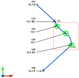
Edit Survey Figure Properties.
      • In the drawing select a figure. On the Figure contextual tab, click Survey Figure Properties
    • Find.
  1. Click to expand the dialog box.
  2. Use the icons to perform editing operations.
  3. In the list view Number or Name column, you can clear the value to disassociate the vertex from the referenced survey point. Enter a new point number or name if necessary. When the Number or Name column is clear, the Easting, Northing, and Elevation columns are enabled and you can edit those values.

To Redraw Adjusted Survey Figures

You can redraw all the defined figures in your survey database based on the current point coordinates.
After you adjust and update survey points, you can update the figures based on adjusted coordinates.
  • In Toolspace, on the Survey tab, do one of the following:
    • To update all figures, right-click the Figures collection Update Figures.
    • To update a single figure, click the Figures collection and in the list view, right- click the individual figure Update Figure.

An overview of pressure pipe networks

Pressure pipe networks are a collection of pipes, fittings, and appurtenances that make up a pressure system, such as a sanitary sewer force main or a water line. All of the parts are dynamic and link together to form a complete network of parts.
Select one of the pipes, and several grips appear, as well as a context-sensitive ribbon. The midpoint grip allows you to curve the pipe if it's not a ductile iron pipe, otherwise it will move the pipe. The context-sensitive ribbon contains tools specific to pressure pipe networks.
Select one of the fittings. Just like a pipe, it also has grips that you can use to edit it, and the context-sensitive ribbon shows you specific options for editing the fitting as well.
On the Toolspace, Prospector tab, expand Pressure Pipe Networks, and then expand Water. All the pressure pipes, fittings, and appurtenances for this drawing are listed here.
On the Settings tab of the Toolspace, expand Pressure Pipe Network, and here is a collection of Parts Lists. This is similar to the parts lists for gravity pipes in pipe networks; however, it contains parts that are specifically designed for pressure pipe networks only. Expand Parts Lists, and in this drawing are two Parts Lists: Water and Standard.
Pressure pipe networks also have three different catalogs to choose from. On theribbon, Home tab, expand the Create Design panel drop-down and select Set Pressure Pipe Network Catalog. In the Set Pressure Pipe Network Catalog dialog, under the Catalog Database File: drop-down, you can choose one of the three different catalog files to create a parts list from: Push on, Flange, and Mechanical parts. Not all part catalogs have the same part. Some contain PVC and HDPE, while another contains only ductile iron. PVC and HDPE are bendable, while ductile iron is not. There are valves only in some lists, while others contain crosses, reducers, caps and other fittings and appurtenances.
Always set the pressure network catalog before you begin creating your parts list for pressure pipe networks. It is recommended to create three parts lists, one for each catalog so you can swap between them as you design. Click Cancel to close the dialog.
Back on the Settings tab of the Toolspace, under Pressure Pipe Networks, right-click the Water parts list and select Edit. You can see that the Parts List has tabs for Pressure Pipes, Fittings, and Appurtenances. Select the Pressure Pipes tab and expand Water. In this tab, there is one type of family for your pressure pipes: ductile iron. Expand ductile iron, and there are several sizes available. Each pipe size has a style associated with it and a render material. To add parts, simply right-click Ductile Iron and select Edit Part Sizes. From here, you can add specific part sizes to your list beyond what you already see.
Similarly, when you select the Fittings tab and expand Water, there are three different types of fittings in the list. When you expand the different fittings types, there are several sizes available and each one has a style associated with it and a render material. Again, you can add sizes by selecting the fitting type, right-clicking, and selecting Add Part Size.
And lastly, select the Appurtenances tab and expand Water. There are two different types of valves in this list. When you expand the different appurtenances, you can see that there are several sizes available, and each one has a style associated with it and a render material. After reviewing the Parts List, click Cancel to close it.
In addition to the parts list, a pressure pipe network has an entire list of commands that you can control the defaults for.
On the Settings tab, there is also a collection for Pressure Pipes. Under Pressure Pipes are the Pressure Pipe Styles, which control the display of the pressure pipes, and the Label Styles for the pressure pipes.
Fittings also have Fitting Styles and Label Styles.
Appurtenances have Appurtenance Styles and Label Styles as well.
All of those settings can be configured and set up for the pressure pipes, fittings and appurtenances, so that when you start laying out your pressure pipe network, all the defaults are correct. You can then save all this information into a template file so that it is ready to be used each time you begin a new drawing.

How to display the cut length of Pressure Pipe

These are specified in the catalog. Open the Content Catalog Editor:
  • 2014: C:\Program Files\Autodesk\Autodesk AutoCAD Civil 3D 2014\Autodesk.Aec.Content.CatalogEditor.exe
  • 2015/2016: C:\Program Files\Autodesk\AutoCAD 201X\C3D\Autodesk.Aec.Content.CatalogEditor.exe
Cut_length
And to label in Civil3D:
Add the following:
<[Cut Length(Uft|P3|RN|AP|GC|UN|Sn|OF)]>
CutLengthLabel.PNG

How to manually transfer AutoCAD user settings

How to manually transfer AutoCAD settings from one computer to another when the specific AutoCAD version does not have the settings export/import utilities. This process can also be used to apply working settings to a specific user account, particularly if that account is unable to initialize AutoCAD due to a redirected profile folder or a similar environment being in place.
 Image result for How to manually transfer AutoCAD user settings

Solution:

User settings in AutoCAD for Windows are stored in two folders and a registry path (in AutoCAD for Mac, see the link referenced below). After installing AutoCAD and running the program once to make sure it works and has gone through its secondary installer process, follow the steps below to copy over the settings to another account or computer:
  1. Exit AutoCAD.
  2. Make a copy of the following two folders in a location accessible by all user accounts:
    For Windows Vista, 7, 8, and 10:
    C:\Users\<user>\AppData\Roaming\Autodesk\AutoCAD 20xx
    C:\Users\<user>\AppData\Local\Autodesk\AutoCAD 20xx
    For Windows XP:
    C:\Documents and Settings\<user>\Application Data\Autodesk\AutoCAD 20xx
    C:\Documents and Settings\<user>\Local Settings\Application Data\Autodesk\AutoCAD 20xx
    Note: These paths contain hidden folders.
  3. Export a copy of the AutoCAD registry key:
    1. Press WINDOWS-R on the keyboard to bring up the Run window, enter REGEDIT and click OK.
    2. Find the following registry key:

      HKEY_CURRENT_USER\Software\Autodesk\AutoCAD\Rxx.x\ACAD-xxxx:40x

      This path is unique for each version of AutoCAD. To see which 'ACAD-xxxx' refers to, select it and then look at the keys on the right side of the Registry Editor. One of the keys will show the install path to the AutoCAD it applies to. The '40x' number signifies the language version of AutoCAD.
    3. Right-click the 'ACAD-xxxx:40x' folder and choose Export.
    4. Enter a file name of your choice, choose a location to save the file, and then click Save.
    5. Close the Registry Editor.
  4. Log in to the destination user account.
  5. Copy over the two folders to their respective locations.
  6. Double-click the .reg file to apply it to the registry. The .reg file can be deleted after use unless you wish to use it again.
Additionally, some support files can be copied directly into the Support folder paths. Following is a generic list. Each product and version may have slightly different paths. Refer to the file paths in Options > Files for the version in question.

Plot Files
C:\Users\[USERNAME]\AppData\Roaming\Autodesk\AutoCAD 201XX\RXX\enu\Plotters
Plotters
C:\Users\[USERNAME]\AppData\Roaming\Autodesk\AutoCAD 20XX\RXX\enu\Plotters\PMP Files
Plot Styles
C:\Users\[USERNAME]\AppData\Roaming\Autodesk\AutoCAD 20XX\RXX\enu\Plotters\Plot Styles
Drawing Templates
C:\Users\[USERNAME]\AppData\Local\Autodesk\AutoCAD 20XX\RXX\enu\Template
Shapes
C:\Users\[USERNAME]\AppData\Roaming\Autodesk\AutoCAD 20XX\RXX\enu\Support


Warning!
Problems caused by improperly editing the Windows registry could render your computer operating system unusable. Microsoft provides a wealth of critical information that you need to know about the registry in the "Microsoft Knowledge Base". Use the Microsoft Registry Editor only at your own risk and only after backing up the registry as outlined for your operating system in the Microsoft article How to back up and restore the registry in Windows and in the related solution How to backup the system registry. Additional information about the registry is also contained in the Help topics in the Microsoft Registry Editor.

How to turn off the Start Tab in AutoCAD

Change the STARTMODE system variable.
  1. Type STARTMODE on the command line in AutoCAD.
  2. Enter 0 (zero) to turn off the Start tab or 1 to turn it on.
Turning it on requires restarting AutoCAD. If you are running AutoCAD in a single document mode (SDI =1), the Start tab will be displayed after you change the value of SDI to 0 and restart AutoCAD.

The Start tab in AutoCAD 2016 replaces the New Tab in AutoCAD 2015 and eliminates the NEWTAB and NEWTABMODE commands.

Thursday, January 23, 2020

To Access and Share Subassemblies

Custom subassemblies that have been created using .NET or VBA can be exported and imported using a package file. Subassemblies created from polylines cannot be included in a package file.
A package file contains all the files necessary for the custom subassemblies to work. Once the package file is created, you can import the package file contents into Autodesk Civil 3D using the ImportSubassemblies command, and copy the custom subassemblies directly into a tool palette or catalog. You can also share a package file with others. For example, you could attach a package file containing one or more subassemblies to an e-mail, or use other file transfer methods.
For more information on creating package files, see "Exporting Custom Subassemblies Using a Package File" in the Developer's Guide.

To copy subassemblies from a package file to a tool palette

  1. Click Home tabPalettes panel.
  2. Open the tool palette that you want to copy the subassemblies into. You may open an existing tool palette or create a new one.
  3. Click Insert tabImport panelImport Subassemblies
  1. Find.
  2. In the Import Subassemblies dialog box, click the folder icon to navigate to and select the package file.
  3. In the Import To section, click Tool Palette, and then select the desired tool palette in the drop-down list.
    Note: You can import the subassemblies to a tool palette and to a catalog at the same time. When you import subassemblies to a catalog, they automatically get imported to the My Imported Tools catalog. If the My Imported Tools catalog does not exist, it is automatically created.
  4. Click OK.
Note: Subassemblies created from polylines cannot be included in a package file. Package files are intended for sharing custom subassemblies that have been created using .NET or VBA.

To copy subassemblies from a package file to a catalog

  1. Click View tabPalettes panelContent Browser.
    Tip: When working with both the Autodesk Civil 3D workspace and the Content Browser, you may find it useful to have the Content Browser window displayed at all times. To do this, right-click in the Content Browser title bar and select Always On Top.
  2. Click Insert tabImport panelImport Subassemblies
  1. Find.
  2. In the Import Subassemblies dialog box, click the folder icon to navigate to and select the package file.
  3. In the Import To section, click Catalog Library/My Imported Tools.
    Note: You can import the subassemblies to a tool palette and to a catalog at the same time. When you import subassemblies to a catalog, they automatically get imported to the My Imported Tools catalog. If the My Imported Tools catalog does not exist, it is automatically created. Once the subassemblies are in the My Imported Tools catalog, you can then copy them to other catalogs.
  4. Click OK.
Note: Subassemblies created from polylines cannot be included in a package file. Package files are intended for sharing custom subassemblies that have been created using .NET or VBA.

Wednesday, January 22, 2020

How to create selectable and searchable text in a PDF from AutoCAD

Causes:

  • An SHX font was used for text. SHX fonts are rasterized (i.e., become a graphic image) when plotted to PDF unless AutoCAD 2016 or newer is used, but then with limitations.
  • The PDF was created by AutoCAD for Mac, in which case both SHX and TTF fonts are raterized during the PDF creation.

Solution:

To have searchable text in a PDF from AutoCAD: 
  1. Use TrueType fonts for text intended to be searchable (mtext, dimensions, etc.).
  2. For TrueType fonts, do not alter the text from the original font, such as changing width (must be 1.0) or other style options.
  3. Make sure the Z coordinate value of the text object is zero.
  4. If SHX fonts are used, set the PDFSHX variable to 1 (for AutoCAD 2017 and later; EPDFSHX for AutoCAD 2016). There is no AutoCAD option or feature to make SHX searchable in a PDF in AutoCAD 2015 and earlier.
TrueType Fonts
Changing text objects so that they have no Z coordinate can be done by using the Express Tools command FLATTEN or by selecting the text and changing the Z value in the Properties palette to zero. Additionally, the following may accomplish this:
  1. At the command line in AutoCAD, enter DVIEW and then select all in your drawing.
  2. Enter PO (POints).
  3. Type in 0,0,0 for the target point.
  4. Type in 0,0,1 for the camera point.
If may be necessary to select the "Capture All" option in the DWG To PDF.pc3 properties:
  1. In the plot window, select DWG To PDF.pc3 for the printer.
  2. Click the Properties button.
  3. In the Custom Properties section, click the Custom Properties button.
  4. Click the "Capture All" option under Font Handling.
  5. Click OK to dismiss the DWG to PDF Properties dialog.
  6. Click OK to dismiss the Plotter Configuration Editor.
  7. Click OK to confirm changes to the PC3 Plotter Configuration file.
SHX Fonts
If using SHX fonts, the latest versions of AutoCAD and DWG TrueView (2016 and newer) can be used to plot to the AutoCAD PDF drivers. All SHX fonts will be converted into PDF comments, which can then be searched in Adobe Reader and other PDF-viewing programs. Usually, the default search/find commands do not include PDF comments in searches, so be sure to change that setting. In the text search box in Adobe Reader, click the gear settings menu and choose "Include Comments."

To move away from having text in PDF comments, there is an application included with Adobe Acrobat called PDFMaker. This does not come with Reader. The full version of Acrobat is required. This application has the ability to generate a placeholder font in the PDF for all the SHX text in an AutoCAD drawing. Using PDFMaker to create the PDF instead of plotting to PDF from within AutoCAD, will result in searchable text in the PDF even, for text which uses an SHX font. There is a toolbar button in AutoCAD for PDFMaker. It is also possible to right-click a DWG file in Windows and choose the "Convert to Adobe PDF" option. DWG files can also be converted to PDF by PDFMaker even if AutoCAD itself is not installed. Please refer to the following Adobe article:

 
The section about AutoCAD is far down the page. There is a jump link at the top which can be used.

PDFMaker only works with certain versions of the AutoCAD DWG format. Here is a chart from Adobe that lists various web browsers and applications, including which versions of AutoCAD they work with (AutoCAD is shown all the way at the bottom of the web page):
 

AutoCAD for Mac products

Starting with version 2018, AutoCAD for Mac can create PDFs with searchable text. Versions prior to 2018 relied upon the built-in PDF creation abilities of the Mac OS, so there was no way to generate a PDF with searchable text. 

AutoCAD mobile app - The place of Innovation

Placing innovation at the forefront

The mission of Structural Surveys Ltd. is to be “digital first” for both its structural survey business and designs for home renovations, additions, and more. When it came to the company’s newly formed design department, the discovery of the AutoCAD mobile app brought design on-site as well as unexpected benefits with workflow, efficiency, and accuracy.

AutoCAD mobile app provides instant solution

Based in Warrington, England, Structural Surveys Ltd. was founded by Andrew Russell to focus on structural surveys of residential and commercial properties, but with a very innovative, digital-based approach and the use of tablets on-site. Since the company was started three years ago, he continually received requests for design work so he branched out to create a design department and recruited structural engineer Chris Caple. And, of course, it also needed a “digital first” approach.
“We were using AutoCAD LT to do design drawings for house extensions, alterations, new builds, and that sort of thing,” Caple says. “But we wanted to step it up to design digitally on-site and quickly, accurately capture all of the structure and geometry.”
Design in AutoCAD LT. Courtesy of Structural Surveys, Ltd.
“I did some research looking at different apps that we could use, and then I came across the AutoCAD mobile app,” he continues. “I realized we already had access to the AutoCAD mobile app because we have a subscription to AutoCAD LT. So, it just made sense to try it out.”
Caple first started to use the AutoCAD mobile app late last year—and hasn’t looked back.
“When you’re with a client, you can move around, and I can chop and change things to show what it's going to look like once the work's complete,” he says. “It's just so easy to use, and you get very accurate drawings. The drawings can then be very quickly opened in AutoCAD LT, and they all scale properly.”
Courtesy of Structural Surveys Ltd.
Since most of Structural Surveys’ design projects are for existing structures, it’s necessary to capture all of the site information. Caple finds this much easier to do with the AutoCAD mobile app.
During a client meeting, Caple will discuss their project on-site, whether it’s a new addition or to knock down a kitchen or dining room wall. He brings his iPad with the AutoCAD mobile app, Apple Pencil, and a laser measurer.
“For a house project, I'll go about measuring up all the relevant rooms using the laser measurer,” Caple says. “Then on my iPad I can draw the building quite quickly, simply, and, most importantly, accurately with the AutoCAD mobile app. I can build up a 2D plan of the house, edit it, and change the placement of the walls or show which ones will be removed or where steel beams will go for support. That’s especially helpful for the client so they can request changes immediately and visualize what the end result will be.”
Design in the AutoCAD mobile app. Courtesy of Structural Surveys Ltd.
With the basic plan drawing in the AutoCAD mobile app, Caple shares it with the team back at the office who open it into AutoCAD LT to add details, especially for construction. From there, a set of drawings for the project is made to hand off to the client.
“The AutoCAD mobile app syncs seamlessly with AutoCAD LT,” Caple says. “It’s just a straight drop from one to the other, which is great because there are no formatting issues and everything is synchronized. It’s hard to ever imagine going back to how we manually did everything before.”

Tuesday, January 21, 2020

To Specify the Rotation of Label Style Components

  1. In the Label Style Composer dialog box, click the Layout tab.
  2. Select a component from the Component Name list.
  3. Change the Rotation Angle value.
  4. Click OK.
Rotation angles are dependent on the Orientation Reference of the label style:
  • Label Orientation Reference set to Object. The rotation angle is measured relative to the X and Y coordinate system as defined by the anchor component direction. For example, if the anchor component direction is 45°, then the rotation angle is measured relative to 45°.
  • Label Orientation Reference set to World. The rotation angle is measured relative to the world coordinate system (X direction = 0° and Y direction = 90°).
  • Label Orientation Reference set to View. The rotation angle is measured relative to the current view (X direction = bottom of screen and Y direction = 90° from bottom of screen).

Setting the Orientation of a Plotted Drawing

Image result for Setting the Orientation of a Plotted Drawing civil
  1. Click the layout tab for which you want to set the drawing orientation.
  2. Click Output tabPlot panelPage Setup Manager.
  3. Find
  4. In the Page Setup Manager, Page Setups area, select the page setup that you want to modify.
  5. Click Modify.
  6. In the Page Setup dialog box, under Drawing Orientation, do one of the following:
    • If your drawing is horizontal, select Landscape.
    • If your drawing is vertical, select Portrait.
    • To rotate 180 degrees, select either Portrait or Landscape, and then select Plot Upside-Down.
  7. Click OK.
  8. In the Page Setup Manager, click Close.

Orientation of contour labels

You added contour labels to your surface’s contour lines and you want to display them with the bottom towards the valley so that the surface height increases in reading direction. However, in the drawing, the labels swap direction so that their orientation always corresponds with the current plan view.

Solution:

To display labels with a fixed orientation, follow these steps:
  1. In Toolspace, on the Settings tab, under Surface, click Label Styles > Contour (or Slope, Spot Elevation, Watershed alternatively).
  2. Select the style you want to modify and right-click. Click Edit.
  3. In the Label Style Composer dialog box, click the General tab.
  4. Expand the Plan Readability node.
  5. Select False from the Plan Readable Value drop-down menu (see image below).
User-added image
  1. Click OK.

Monday, January 20, 2020

Exporting labels to a text file

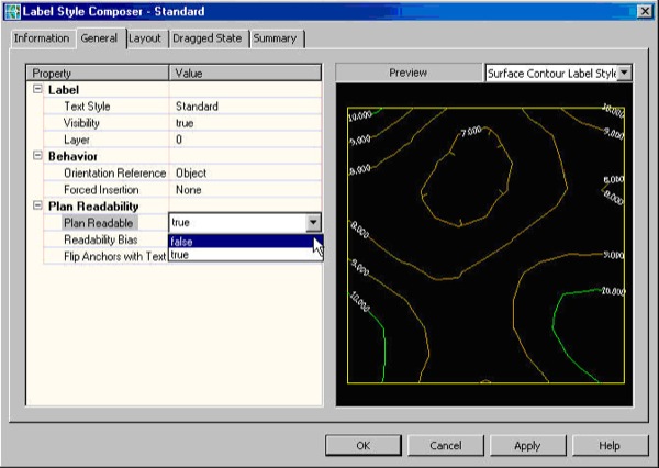
You want to know how the content of a label can be exported to a text file in Autodesk® AutoCAD® Civil 3D®.
User-added image

Solution:

  • Export the drawing to DXFUser-added image
  • The content of the labels can be found as text in the fileUser-added image


Friday, January 17, 2020

About Saving Drawings

Save drawing files or selected objects just as you do with other applications. You can also control automatic saves and backup files.
When you work on a drawing, you should save it frequently. Saving protects you from losing work in the event of a power failure or other unexpected event.
The file extension for drawing files is .dwg, and unless you change the default file format in the Options dialog box, drawings are saved in the latest drawing file format. By default, the program creates a backup file of the previous version of your drawing folder each time you save. Experienced users consider it a best practice to leave backups turned on.
Should you ever need to revert to the previous version, you can rename the .bak file that's in the same folder as your drawing to a file with a different name and a .dwg file extension.
Note: The character limit for a DWG file name (including its path) is 256 characters.

The QSAVE, SAVEAS, and SAVE Commands

Depending on what you want to accomplish, there are several useful differences between these commands.
  • QSAVE. If the current drawing has already been saved at least once, the program saves the drawing and does not request a new file name. If the current drawing has never been saved, the Save Drawing As dialog box displays. The Save icons in the user interface all use the QSAVE command.
  • SAVEAS. Saves a copy of the current drawing under a new file name or location. The new file name or location becomes the current drawing and the previous drawing closes without saving any changes to it.
  • SAVE. In AutoCAD, if the drawing has been previously saved, saves the current drawing to the file name or location that you specify, but leaves the current drawing unchanged. In AutoCAD LT, the SAVE command is identical to the SAVEAS command.

Change the Default Drawing Folder

Each time you start the product, the last folder that you used for opening or saving a file is set as the default path in the standard file selection dialog box. Alternatively, you can specify a fixed default folder with the program shortcut icon in Windows. For specific instructions, see the topic To Change the Default Drawing Folder below.

Access Your Drawings Remotely

You can save and open specified drawing files online with Autodesk Web & Mobile, which is accessible from any of your internet-connected devices. The primary intent of this feature is for convenient access to your drawing files from remote devices as an alternative to emailing your drawing files to yourself.
The commands for saving and opening files from your online account are available from the Quick Access toolbar.
Drawing file sizes are limited depending on your account. Drawings in free accounts can be up to 10 MB in size.
When you upload a drawing with external references to your Autodesk Web & Mobile Account:
  • The files are packaged in a compressed format (*.dwgzip) together with its referenced files. When an uploaded drawing package is unpackaged, it does not recreate a folder hierarchy. The drawing and its references are in a single folder.
  • External references are limited to xrefs (.dwg files) and image files only. No other reference or support files are included in the package. If you need to modify a referenced drawing, save it separately to your Autodesk Web & Mobile Account.
  • Online plotting is limited to PDF format.
Use the eTransmit feature to package a complete set of files and avoid missing files when sharing drawings with others outside of your company. However, when sharing copied files, remember that version control is minimally based on date and time. Modifying the same file simultaneously on multiple devices can lead to version control problems.
Note: This feature is available only on 64-bit systems.

Automatic Saves

By default, the program automatically saves your drawing 10 minutes after the last time it was saved. You can increase or decrease the time between automatic saves, or you can turn off automatic saving from the Options dialog box, Open and Save tab. Saves are normally incremental saves, which are noticeably faster than full saves in larger drawings. Incremental saves result in temporarily larger file sizes until a full save is triggered by the ISAVEPERCENT system variable, which optimizes the drawing's file size.
Note: To force a full save, set the ISAVEPERCENT system variable to 0 and save the drawing. Saving to a different format always results in a full save.

Manage the Size of Drawing Files

In some circumstances, the size of drawing files can become larger than expected. The following list provides you with common possibilities.
  • Many incremental saves (refer to the ISAVEPERCENT system variable)
  • Large hatches, especially if they have been exploded
  • Large 3D meshes
  • Unused DGN line styles or other orphaned data
  • A large number of proxy objects
  • A large number of block definitions or a few large-sized block definitions
  • A large number of scales defined for layout viewports, page layouts, and plotting (refer to the SCALELISTEDIT command)
  • A large number of layer filters (refer to the FILTERS command)
  • A large number of registered applications
The PURGE or -PURGE commands will fix most of these problems. Additional steps you can take include the following:
  • Use the AUDIT command to remove any corrupt objects
  • Use the WBLOCK command, selecting all objects, and save them as a new drawing file
  • Save the drawing in DXF format (ASCII option) for further investigation using a text editor (advanced)
A good practice is to create several smaller drawings. Use the XREF command to merge them into a master drawing, and then do your work in the smaller drawings.

Work Internationally

If you share drawing files with offices or companies in other countries and regions, the drawing file names might contain characters that are not used in other languages.
If a drawing file is created in a different language version of the operating system, the following will occur:
In either case, you will be able to open the drawing file in AutoCAD 2007-based products and later releases.
  • If the language is installed, the file name characters are visible in Windows Explorer or File Explorer.
  • If the language is not installed, the file name characters appear as a series of boxes in Windows Explorer or File Explorer, and a dialog box offers to install the language pack.
Note: If you share drawing files with companies using earlier releases of the product, you can avoid file name issues for Asian languages and languages that use accented characters. In those circumstances, do not use high ASCII values, or values of 80 hexadecimal and above, when creating a file name.

Analyzing Surfaces

Surface analysis tools check the continuity, curvature and draft angles of surfaces.
Use the surface analysis tools to validate surfaces and curves before manufacturing. Analysis tools include:
  • Zebra Analysis. Analyzes surface continuity by projecting parallel lines onto the model.
  • Curvature Analysis. Evaluates areas of high and low surface curvature by displaying a color gradient.
  • Draft Analysis. Evaluates whether a model has adequate draft between a part and its mold.
Note: Analysis tools only work in the 3D visual styles; they do not work in 2D.

To Create a Curve on a Figure Using Point of Curvature

Specify that the next shot is a Point of Curvature (PC) in the current figure. The shot immediately following the next shot is on the Point of Tangency (PT). This command creates a tangential arc from the last leg in the figure.
  1. In Toolspace, on the Survey tab, right-click a named network Survey Command Window.
  2. At the Command line, enter:
    PC

Command Line Example

PC
AD 13 30 25 ! Shot on PC
AD 14 33 24 ! Shot on PT
END
The following illustrates the Point of Curvature command:

Command Syntax

PC

Thursday, January 16, 2020

Curve

Curve
Insert a curve between two points.

Properties

Specify the following parameters in the Properties panel.
Link
Link Number Specifies the link number. You can change the automatically generated Link Number value.
Link Codes Specifies the codes assigned to the link.
Geometry Type
Creation Type Specifies the type of curve to draw:
  • Arc: General
  • Arc: 3 Points
  • Parabola: General
Arc Tessellation Specifies the number of line segments used to represent the curve.
Note: This value must be between 2 and 100.
Click [...] to open the Expression Editor, where you can enter or calculate a value.
Geometry Properties
Start Point Specifies the start point of the curve.
Center Point (Arc: General) Specifies the center point of a general arc.
Arc Point (Arc: 3 Points) Specifies the through point of a three-point arc.
End Point Specifies the end point of the curve.
Mid-Ordinate (Parabola: General) Specifies the distance between the lowest point of a parabola and its vertex.
Click [...] to open the Expression Editor, where you can enter or calculate a value.
Miscellaneous
Comment Indicates notes about the curve. Comments can be displayed in the Preview panel.

Examples

To see examples of how this geometry element is used, open the following Sample PKT file:
Curve Example.pkt
The example PKT contains three curves. In the Flowchart, each curve is constructed in a separate sequence. Each curve type is defined by a start point, an end point, and a parameter. To review the curve parameters, select the curve in the Flowchart, and then check the Geometry Properties section of the Properties panel.
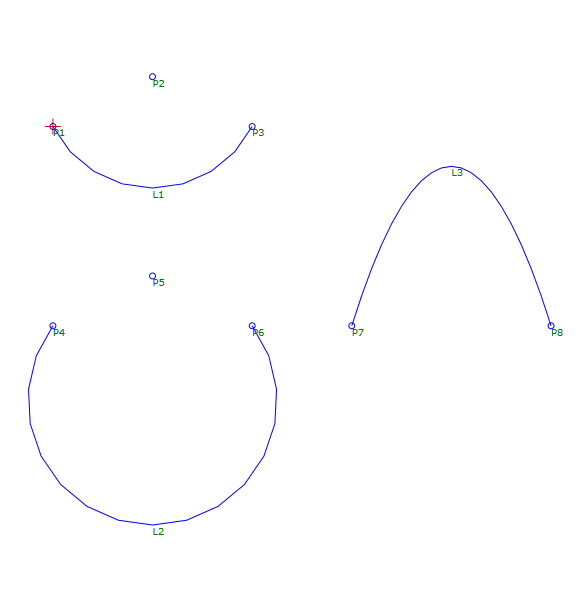
Working with Custom Render Presets

Display the Render Presets Manager

Do one of the following to display the Render Presets Manager palette:
  • Click View tab Palettes panel Render Presets Manager.
  • Find
  • Click Visualize tab Render panel Dialog box launcher.
    • Find
    • At the Command prompt, enter rpref.

    Create a Custom Render Preset

    1. Display the Render Presets Manager palette.
    2. On the Render Presets Manager palette, click the Current Preset drop-down list select an existing render preset.
    3. Click Create Copy.
      The new render preset is set current and available for edit.
    4. Modify the render preset as needed.
      The changes made to the render preset are automatically saved.

    Modify a Custom Render Preset

    1. Display the Render Presets Manager palette.
    2. On the Render Presets Manager palette, click the Current Preset drop-down list and select the custom render preset to modify.
    3. Do any of the following:
      • In the Name text box, enter a new meaningful name.
      • In the Description text box, revise the description to provide a summary of when to use the render preset.
      • In the Render Duration section, select the type of iterative rendering to use. If you select Render By Level or Render By Time, adjust the number of levels (iterations) or time to specify the quality of the rendering.
      • In the Lighting and Materials section, select the rendering accuracy to use for lighting and materials.
    4. The changes made to the render preset are automatically saved.

    Delete a Custom Render Preset

    1. Display the Render Presets Manager palette.
    2. On the Render Presets Manager palette, click the Current Preset drop-down list and select the custom render preset to remove.
    3. Click Delete.