Thursday, August 29, 2019

Receiving Notification of New Layers

You can have a drawing automatically notify you if any new layers have been added to it.
New layers might be added when you attach external references or insert blocks. Also, if you work with shared drawings, new layers might be added by other contributors.
When the layer notification feature is turned on, and a new layer is subsequently added, a balloon or dialog box message appears after specified operations that involve files, layers, or plotting. The status bar also displays an icon that alerts you to new layers.
When a new layer is added, you will want to make sure that it displays and prints as intended, especially if you use special layer settings for plotting, or if you set property overrides in layout viewports. Here is the general process:
  • In the Layer Properties Manager, click the group filter named Unreconciled New Layers.
  • Review and revise the property settings for each new layer to make sure that it displays and plots as intended.
  • Accept the layer as reconciled, which removes the layer from the layer filter list.
The Unreconciled New Layers filter is automatically created when the layer notification feature is turned on, and a new layer is subsequently created or generated.
The new layer notification feature can be controlled from the Layer Properties Manager, Settings button.

How to create a macro for reconciling layers in AutoCAD

When opening a drawing, AutoCAD shows the following message and you would like to know of an easy way to do the reconciliation: 

Unreconciled New Layers
New layers were found that may need to be reconciled

 
User-added image

Solution:

Layers can be reconciled by selecting them in the layers palette and then right-clicking and choosing "Reconcile layers." To automate this, you may create a macro button to do it and attach it to a toolbar:
  1. Execute the CUI command.
  2. In the command list, click to create a new command.
User-added image
  1. On the right pane, type a name for the new command (such as Reconcile).
  2. Define the macro to execute.
  3. Assign an icon for the new command.
User-added image
  1. Drag and drop the new command from the command list to a toolbar.

Tuesday, August 27, 2019

Creating a DXB File

DXB (drawing interchange binary) file formats are supported using the DXB non-system file driver. This is commonly used to “flatten” 3D drawings to 2D.

The output is compatible with the DXBIN command and with the ADI DXB driver delivered with earlier releases. The DXB driver shares these limitations of the ADI driver:
  • The driver produces 16-bit integer DXB files containing only vectors.
  • DXB output is monochrome; all vectors are color 7.
  • Raster images and embedded OLE objects are not supported.
  • The driver ignores object and plot style lineweights.
  1. Make sure you have configured a plotter driver for DXB file output.
  2. Click Output tabPlot panelPlot Find
  3. In the Plot dialog box, under Printer/Plotter, in the Name box, select a DXB format configuration from the list.
  4. Select plot settings for the DXB file as needed.
  5. Click OK.
  6. In the Browse for Plot File dialog box, select a location and enter a file name for the DXB file.
  7. Click Save.

To Plot a DWF File

You can create DWF (2D vector) files to publish your drawings on the web or across an intranet.

DWF files can be opened, viewed, and plotted by anyone using Autodesk ® Design Review. With the DWF file viewer, you can also view DWF files in Microsoft ® Internet Explorer 5.01 or later. DWF files support real-time panning and zooming as well as control over the display of layers and named views.
  1. Click Output tabPlot panelPlot Find
  2. In the Plot dialog box, under Printer/Plotter, in the Name box, select the DWF6 ePlot.pc3 configuration from the Name list.
  3. Select plot settings for the DWF file as needed.
  4. Click OK.
  5. In the Browse for Plot File dialog box, select a location and enter a file name for the DWF file.
  6. Click Save.

Corridor Sections

You can use the Corridor Section Editor to view and modify corridor sections and to visually inspect how assemblies are applied at various stations.
Use the Corridor Section Editor to apply assembly overrides to a corridor section or a range of sections and then view only those sections. To view both the corridor section view and its location along the corridor (1), open two horizontal viewports.
Following is a simple corridor section as viewed with the Corridor Section Editor:
You can also view complex corridors that are modeled with multiple baselines. You can step through corridor stations or jump to any station of interest.
Edit corridor and assembly parameters as required, using the following methods:
  • Edit the assembly numerically by editing the subassembly parameters.
  • Edit the assembly manually by adding links and points to the subassembly part geometry.
  • Resize assembly parameters by grip editing the subassembly part geometry.
  • Insert or remove subassemblies from a corridor section.
Overriding assemblies may require you to edit the way points, links, and shapes are represented in the corridor as feature codes. Use the Edit User Defined Codes command to change or delete codes as required.
If you have edited a subassembly by either adding or deleting a point, adding or deleting a link, or editing the subassembly geometry using grips, you cannot edit the values of the changed parameters in the Corridor Section Editor.

Cannot build multiple corridor surfaces in Civil 3D - SOLVED

 Go into Corridor Properties, Surfaces tab 
2. Click on Name Template button to get into the dialog 
3. Set property fields to “Next Corridor Surface Counter”  
User-added image 
4. Apply changes 
5. Create Corridor Surface 

To Merge two different grading surfaces in Civil 3D

Merging of gradings or grading surfaces does not work in Civil 3D it is a program limitation.

Solution:

  • If you want to merge or have gradings interacting they need to be placed in the same site. However, the results might not look as expected
  • The following workaround can be applied to merge overlapping grading surfaces:
    • Create a new and empty surface in Civil 3D
    • Use "EditSurfacePaste" to insert the Existing Ground (EG) and the Grading Surface 1
    • Create a Crop Surfcace the does not contain the overlapping surface areas between Grading Surface 1 and 2
    • In a new DWG insert the Crop Surface and create/add Grading Surface 2 

Monday, August 26, 2019

How to Reset Points in Civil 3D

Reset the point marker and label to their original location and rotation angle.

To reset point location and rotation

  1. Select the point you want to reset.
  2. Hover the cursor over the  grip. Click Reset All.

To reset point marker

  1. Select the point you want to reset.
  2. Hover the cursor over the  grip. Click Reset Marker Rotation.

To reset a point label

  1. Select the point you want to reset.
  2. Hover the cursor over the  grip.
  3. Click one of the following:
    • Reset Label Location. Returns the label to the original X-Y location.
    • Reset Label Rotation. Returns the label to the original, as-composed rotation angle.
    • Reset Label. Returns the label to the original X-Y location and as-composed rotation angle.

Saturday, August 17, 2019

Selecting Multiple Objects

At the Select Objects prompt, you can select many objects at the same time.

Specify a Rectangular Selection Area

Specify opposite corners to define a rectangular area. The background inside the area changes color and becomes transparent. The direction that you drag your cursor from the first point to the opposite corner determines which objects are selected.
  • Window selection. Drag your cursor from left to right to select only objects that are entirely enclosed by the rectangular area.
  • Crossing selection. Drag your cursor from right to left to select objects that the rectangular window encloses or crosses.
With a window selection, usually the entire object must be contained in the rectangular selection area. However, if an object with a noncontinuous (dashed) linetype is only partially visible in the viewport and all the visible vectors of the linetype can be enclosed within the selection window, the entire object is selected.

Specify an Irregularly Shaped Selection Area

Specify points to define an irregularly shaped area. Use window polygon selection to select objects entirely enclosed by the selection area. Use crossing polygon selection to select objects enclosed or crossed by the selection area.

Specify a Selection Fence

In a complex drawing, use a selection fence. A selection fence looks like a polyline and selects only the objects it passes through. The circuit board illustration shows a fence selecting several components.

Use Other Selection Options

You can see all selection options by entering ? at the Select Objects prompt. For a description of each of the selection options, see the SELECT command.

Remove Selection from Multiple Objects

You can enter r (Remove) at the Select Objects prompt and use any selection option to remove objects from the selection set. If you are using the Remove option and want to return to adding objects to the selection set, enter (Add).
You can also remove objects from the current selection set by holding down Shift and selecting them again, or by holding down Shift and then clicking and dragging window or crossing selections. You can add and remove objects repeatedly from the selection set.

Adding a shortcut to your Select File dialogs in AutoCAD

To add a shortcut to the Select File "Places" sidebar, do one of the following: 

Drag the folder to the Places sidebar:
  1. Execute the OPEN or SAVE command.
  2. Browse to the folder location to be added.
  3. Select and drag the folder to the left-side "Places" panel.
  4. Drop the folder in the preferred position in the panel.
User-added image 

Add the Current folder:
  1. Execute the OPEN or SAVE command.
  2. Browse to the location of the project files.
  3. Right-click over the "Places" sidebar and choose "Add current folder."
  4. The folder can then be dragged to the desired location in the list. 
User-added image 

Add the folder by typing the path:
  1. Execute the OPEN or SAVE command.
  2. Browse to the location of the project files.
  3. Right-click over the "Places" sidebar and choose "Add..."
  4. Enter the item and/or path. 
  5. Click OK
User-added image 

Thursday, August 15, 2019

AutoCAD file save process

Given initial files on disk: Model.DWG and Model.BAK:

Opening a drawing

  1. OPEN the Model.DWG.
  2. Model.DWG is loaded from disk into RAM.
  3. Model.DWL (WhoHas file) created.
  4. Model.DWL2 (XML version of WhoHas file) created.
Note: No .tmp is created on OPEN.

Full save

  1. Full SAVE (occurs if ISAVEPERCENT=0 and may also occur if ISAVEPERCENT>0).
  2. SAVE the Model.DWG if a full-save occurs and SAVEBAK sysvar is enabled.
  3. Model.DWG in RAM is written out to a .tmp.
  4. Model.BAK deleted.
  5. Model.DWG renamed to Model.BAK.
  6. The .tmp renamed to Model.DWG.
  7. Model.DWG remains in RAM for current session.
Model.DWL & Model.DWL2 remain as-is (until user closes Model.DWG, at which time they are deleted).

Incremental save

  1. Incremental SAVE (which may occur if ISAVEPERCENT>0).
  2. SAVE the Model.DWG when SAVEBAK sysvar is enabled.
  3. Model.DWG copied to a .tmp.
  4. Model.DWG edits (changes currently in RAM since last save) are written incrementally the .tmp.
  5. Model.BAK deleted.
  6. Model.DWG renamed to Model.BAK.
  7. The .tmp is renamed to Model.DWG.
  8. Model.DWG remains in RAM for current session.
Note: Save performance is improved in AutoCAD 2018. Objects that will experience the greatest improvement include blocks with annotation scaling, mtext with columns and other newer formatting, as well as attributes and attribute definitions with multilines. In addition, automatic save functionality is updated so that saves are most often performed incrementally rather than performing full saves, which are slower.

Understanding backup and autosave files in AutoCAD

Backup (.bak) Files

Drawing backup files are typically created every time a .dwg file is manually saved. By default the file will be saved in the same location as the .dwg and will have the same name as the drawing but with a .bak extension, such as, site_topo.bak. A backup file is an exact copy of the drawing file prior to the last save. As such, backup files are always one version older than the currently saved drawing. Only one backup file is retained at a time so newly created backups will always replace older backups of the same name.
Note: Backup files are created only if the system variable ISAVEBACK is set to 1.
Backup files are essentially renamed .dwg files. Data saved in .bak files can be recovered by renaming the .bak extension to .dwg and then opening that file in AutoCAD.
MOVEBAK Command
Included in the AutoCAD Express Tools is the MOVEBAK command which permits specifying an alternative folder for the bak files when created. To keep bak files in a single location—as opposed to keeping them in the same folder as the associated drawings—use the MOVEBAK command to specify another folder and all bak files will be automatically moved there when created. Enter "." as a value in the command to reset AutoCAD to the default behavior.
Note: MOVEBAK is only available in Autodesk products that include the AutoCAD Express Tools. The MOVEBAK command has not been updated in recent years so it may not support paths with embedded spaces.

Automatic Save (.sv$) Files

Automatic save files—commonly referred to as "autosave" files—are backup files created automatically by the Autosave feature. Automatic save is enabled by default and the number of minutes between automatic saves can be set in the Open and Save tab in the Options dialog box or by using the SAVETIME system variable. Automatic saves are only done if a drawing has been modified after the last save. An automatic save will not save to the current drawing. Instead, a temporary file with the extension .sv$ is generated. QSAVE, SAVE, and SAVEAS will delete the current .sv$ file and halt the automatic save timer until an edit is made to the drawing.
If AutoCAD crashes or is otherwise abnormally terminated during a session, data saved in .sv$ files can be recovered by locating the autosave file, renaming the .sv$ extension to .dwg and then opening that file in AutoCAD. The autosave file will contain all drawing information as of the last time autosave ran. When AutoCAD closes normally, .sv$ files are deleted as any open drawings would be closed/saved normally.
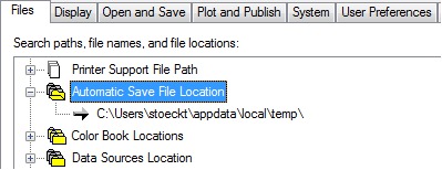
The location of autosave files in the Windows operating system can be determined by going to the Files tab in the Options dialog box and inspecting the Automatic Save File Location folder in the hierarchy, or by using the SAVEFILEPATH variable. In the Mac OS, this can be found under the Application tab in Preferences.
By default in Windows, the location is taken from the TEMP environment variable in the operating system. An easy way to open the user Temp folder is to type %tmp% in the Start menu search or in the location bar of any folder window. In the Mac OS, the default location is in the user's folder within /Documents/Autodesk/Autosave.
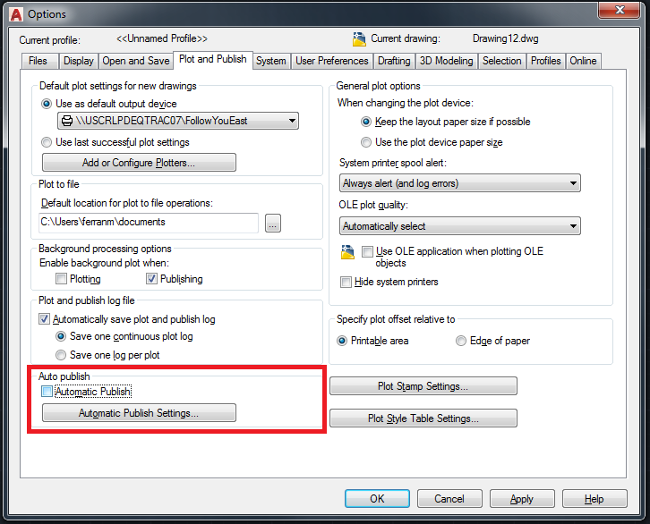
Automatic save can be disabled by unchecking Automatic save in the Open and Save tab in the Options dialog box or by setting the SAVETIME system variable to 0. Disabling automatic save prevents AutoCAD from automatically creating sv$ files while working. In the event of a crash, there will be no interim files to use for data recovery.
Tip: The TIME command is useful in tracking whether an automatic save file will be created because it gives information about the countdown time and whether modifications have been made to the drawing.

Temporary (.ac$) Files

By default, temporary files have an .ac$ extension. These files contain information that is used by various AutoCAD commands (such as UNDO) and do not contain any drawing data that can be recovered. They should only exist during an AutoCAD session but may be left behind if AutoCAD crashes or is abnormally terminated.

Drawing Recovery Manager

Originally introduced in AutoCAD 2006, the Drawing Recovery Manager (DRAWINGRECOVERY) helps with the task of locating and opening drawings that were last open when AutoCAD crashed, as well as any backup and autosave files associated with those drawings.
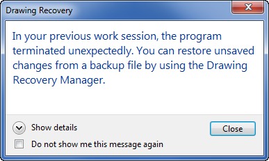
When launching AutoCAD after a crash, the Drawing Recovery Manager determines what drawings were active when the crash occurred and displays those drawings, and the associated backup and autosave files, in a single interface.
The Drawing Recovery Manager can open backup and autosave files directly into the current session of AutoCAD without having to manually locate and rename those files. The first time a saved backup or autosave file is opened from the Drawing Recovery Manager, a prompt to rename the file will be shown.
Note: The Drawing Recovery Manager is only useful after a crash has occurred and will only display information about drawing files that were active during a session that crashed. The Drawing Recovery Manager cannot be launched during a normal working session to show the backup and autosave files for the current drawing.
Tip: On the Mac OS, drawings or recovered files after a crash can be locked and need to be unlocked in the Finder using Get Info and disabling the Locked checkbox.

Label Contour Lines

You can label contour lines to indicate their elevations. Contour labels display in site plan views.
  1. Create a topographic surface with different elevations.
  2. Open a site plan view.
  3. Click Massing & Site tabModify Site panel (Label Contours).
  4. Sketch a line that intersects one or more contour lines.
Labels display on the contour lines. (You may need to zoom in to see the labels.) The label line itself is not visible unless you select a label.

Example

Working with Linked Topography

You can use linked topography in many of the same ways that you can use topography created in Revit.
To link topography to your model, click Insert tabLink panel (Link Topography).

Using linked topography in the model

One topography link may include multiple surfaces. You can treat each surface separately.
You can do the following with the linked topography surfaces:
  • Assign a different phase to each surface.
  • Display the topography in a view, and place it on a sheet.
  • Create a section view that cuts the topography. Display poché below the surface.
  • Specify contour settings and display contour labels on the topography.
  • Place building pads and site components on the topography.
  • Place railings on the topography. They follow its surface.
  • Create subregions and assign materials to them.
  • Add spot dimensions (such as spot elevations and spot slopes) to a surface.
  • Include topography data in a schedule.
Note:
  • Place building pads or subregions on a single surface. They cannot span multiple topography surfaces.
  • For linked topography, you can use the Subregion tool. However, you cannot use these tools: Split Surface, Merge Surfaces, and Graded Region.

Visibility and graphics for linked topography

You can control the visibility and graphics of linked topography as follows:
  • Visibility/Graphics: Use the Visibility/Graphics dialog to control the display of the topography in each view. For example, you can display or hide the topography, change its graphics, and more. In a 2D view or a 3D view, on the Visibility/Graphics dialog, click the Model Categories tab, and expand the Topography category to turn visibility on or off, and to define graphics settings.
  • Assign a material to the topography.
    Topography elements do not support surface patterns assigned to materials.

Managing linked topography

To manage topography links, use the Manage Links dialog.
  • Reload: When you reload a topography link, all hosted elements are restored to the topography surface. For example, railings and building pads remain in their respective positions on the surface.
    If a reloaded surface has changed so that a hosted element is no longer positioned on it, a warning displays so you can investigate and correct the issue. If some surfaces in the reloaded topography no longer exist, you see a list of the deleted surfaces.
  • Reload from: Use this option to reload a topography link from another location.
  • Remove: If you remove a topography link, the elements that it hosts are also deleted. A warning dialog indicates how many elements are affected. Expand the list to see element details. To avoid deleting the hosted elements, cancel the Remove operation.