Wednesday, October 31, 2018

How To Import Keyhole Markup Language (Google Earth KML) Files

 KML is a file format used to display geographic data within Internet-based, two-dimensional maps and three-dimensional Earth browsers.
To import from Google KML
  1. Click Insert tabImport panelMap Import .
  2. In the Import Location dialog box, under Files Of Type, select Google KML.
  3. Select the file or folder to import. Click OK.
  4. In the Import Dialog Box, under Spatial Filter, specify whether to limit the area where data will be imported:
    • None — Place no area limits on the incoming file.
    • Current Display — Limit the import to the current drawing area.
    • Define Window — Limit the import to an area you define. To use this option, click Select. Respond to the prompts to define the area.
  5. Specify the import settings for each input layer (see the Import dialog box for details).
    • Drawing Layer— Select a target layer for each layer in the incoming file.
    • Object Class— Assign incoming objects to an existing object class and map incoming attribute data to the data fields in the object class. The Object Class fields are available only if you have object classes defined in your map.
    • Input Coordinate System— Specify the coordinate system of the incoming file. If the drawing has a coordinate system assigned to it, incoming objects are converted to the coordinate system of the drawing.
    • Data— For each layer, specify how to import data.
    • Points— For each layer, specify how to treat incoming point objects.
  6. By default, polygons are imported as polygon objects. To import them as closed polylines, select Import Polygons As Closed Polylines.
  7. Click OK to begin the import process.

Using Annotative Text and Dimensions in AutoCAD Civil 3D

Issue:

You want to use the same text and dimensions to display the same information in different viewports at different scales.


Solution:

Make the text or dimensions annotative and apply the appropriate scales. 


Method 1:

  1. Insert text or dimension
  2. In the Properties palette, change the "Annotative" setting to "Yes"
  3. Launch the Annotative Object Scale dialog from the "Annotative scale" setting (click the "..." next to the current scale)
  4. Add necessary scales, then OK


Method 2:

  1. Select an Annotative Style for the text or dimension
  2. In paperspace, set viewports to the appropriate scale to display Annotative Objects of the same scale.

Toggle Annotation Visibility and "Automatically add scales to annotative objects when the annotation scale changes" as needed.


Modify the Scale of Specific Linetypes in AutoCAD

Issue:


There may be a need to scale individual linetypes in a drawing so that they appear smaller or larger depending on the need. Changing the LTSCALE will modify all linetype scales in the drawing, so how can one be selective and scale one or more linetypes?

Solution:


The solution is to select the linetype and then modify the scale in the Properties palette. In Properties, when no objects are selected the Linetype Scale field under the General category will scale linetypes globally in the drawing. To only scale select linetypes, select one or more existing line entities in the drawing and then change the Linetype Scale in the Properties palette. 


Adding breaks to dimension lines in AutoCAD

Issue:

How do you add breaks to dimension extension lines when the extension lines cross over other lines? 


Solution:

Use the DIMBREAK command and select one or more dimensions and then use the Manual or Auto options to add the breaks in the dimension extension lines.

Moving AutoCAD or COGO Points Perpendicular to Line


Issue:

You want to know if there is a way to move a large number of surveyed cogo points (can be AutoCAD points) perpendicularly until they intersect a line. 

Solution:

  1. Set a new UCS make sure that the X-axis of the new UCS is on the line you want the points to be moved or transferred.
  2. Then select all the points which is on the same direction as the new X-axis and move them to that line
  3. In the properties manager set all their Y values to zero.
  4. Repeat step 1-3 if there are multiple directions.

How to Add Users in the New View

Autodesk Account allows you to add users individually or in bulk, and assign products during the process. When you add a user, they will receive a confirmation email that tells them how to create an Autodesk account with their own password. Through their account, users can then download products and access support.
Note: Do not use double-byte numbers in user names, they are not supported. 

Add Users (Procedure)

  1. Sign in to Autodesk Account at manage.autodesk.com and click User Management > By User in the left navigation menu. You will only see User Management if you are an administrator.

    Note: If your screen looks different than the image below, you may be in classic user management.
  2. Click on the Users icon in the left-hand navigation menu.
  3. Enter the user's first name, last name and email address separated by a comma and a space (for example, David, West, david.west@email.com). Separate multiple users with a semicolon (for example, David, West, david.west@email.com; Becky, Hill, becky.hill@email.com).
  4. Click Send Invite. The user's status will show as pending until they accept the invitation. They will not have access to any products or services until you assign them. 

    Note: The invitation expires in 30 days.

Tuesday, October 30, 2018

'Mirror' Command in AutoCad Civil 3D

Creates a mirrored copy of selected objects.
 Find
You can create objects that represent half of a drawing, select them, and mirror them across a specified line to create the other half.

Note: By default, when you mirror a text object, the direction of the text is not changed. Set the MIRRTEXT system variable to 1 if you do want the text to be reversed.
The following prompts are displayed.
Select objects
Use an object selection method to select the objects to be mirrored. Press Enter to finish.
Specify first point, second point of mirror line
The two specified points become the endpoints of a line about which the selected objects are mirrored. For mirroring in 3D, this line defines a mirroring plane perpendicular to the XY plane of the user coordinate system (UCS) containing the mirror line.
Erase source objects
Determines whether the original objects are erased or retained after mirroring them.

How to Download Rail Layout 2017

'Issue':

In the previous version, the Rail Layout module often be included in Civil 3D Productivity Tools.  However , In Civil 3D 2017 Productivity, it cannot be foundd. So, you have the necessity to know where to download it.


'Solution':

Rail Layout Module for Civil 3D 2017 is a part of Civil 3D  Enhancement, you  could download and install the enhancement from below link:
http://up.autodesk.com/2017/CIV3D/C3D_2017_V1_Enhancements_x64.exe 

How to Create New Layer Filters

You can use layer filters to control which layers names are listed in the Layer Properties Manager.
Open the Layer Properties Manager. You can see that the Filters list already includes several layer filters. Layer filters are used to control which layer names are displayed in the Layer Properties Manager and can also be used to limit the layers displayed in the Layer control drop-down in the Layers panel of the Home ribbon.
For example, when you select the Architectural filter, the layer list immediately changes. It now shows only those layers that begin with the characters "A-". When you expand the Layer drop-down in the Layers panel on the Home ribbon, it too has had this filter applied.
In the Filters panel, select All so that you once again see all of the layers.
You can filter the layer list in a number of ways.
For example, you can use the Search for layer field, located in the upper-right corner of the Layer Properties Manager, to quickly filter the display of layers by name. When you click inside this field, it initially contains an asterisk (*). This is a wildcard that tells the program to search for all characters. Type "*wall* ". The layer list is immediately sorted so that it contains only those layers that contain the word "wall". Expand the Layer drop-down and note that this quick filter is not applied to the layers in the drop-down, however.
In the Layer Properties Manager, click the X adjacent to the search field to clear the quick filter. Note that any quick filters are also discarded when a new search string is entered or you close the Layer Properties Manager.
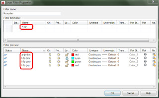
You can also create and save layer filters based on layer properties. To do this, click the New Property Filter button to display the Layer Filter Properties dialog. In the Filter name field, enter the name you want to use to define the filter. For example, type "Walls ". Then, in the Filter definition area, click in the Name column and then type "*wall* ". The Filter preview list immediately updates to display a preview of the results. Click OK to close the Layer Filter Properties dialog. You can see the new Walls filter in the Filters list and the layer list includes only those layer names that contain the word WALLS. And when you expand the Layers drop-down, it includes only the current layer and those same layers that include the word WALLS.
You can also delete layer filters. In the Layer Properties Manager, right-click the Walls filter you just created. Tools in the menu enable you to change layer properties, rename or delete the filter, or open the Layer Filter Properties dialog. Choose Delete to immediately delete the filter. Note, however, that you cannot delete any of the predefined filters, such as All and All Used Layers.
You can also create nested filters. For example, in the Filters list, select the Architectural filter, right-click, and choose New Properties Filter… and then create the Walls filter again. In the Filter name field, type "Walls ". In the Filter definition list, click in the Namecolumn and type "*wall* ". Then, click OK. This time, the Walls filter is nested below the Architectural filter. This can be a handy way to organize filters in complex drawings, since you can easily collapse or expand branches in the filters tree list.
You can filter using any layer properties you wish. Right-click the Walls filter and choose Properties… from the shortcut menu to return to the Layer Filter Properties dialog to modify the Walls filter. In the Filter definition list, click in the Linetype column and then click the small button to open the Select Linetype dialog. Now you can add a linetype to the filter. Choose the CONTINOUS linetype and then click OK. As soon as you do, the Walls filter changes. It now only lists layers whose names contain the word "walls" and that have the continuous linetype. So the layer that used the hidden linetype is no longer included in the filtered list of layers. Click OK to close the Layer Filter Properties dialog.
You can also filter using multiple properties. In the Filters list, right-click the Walls filter and choose Properties… to open the Layer Filter Properties dialog. In the Filter definition list, right-click the filter and choose Duplicate Row. Now you see two copies of the filter definition. On the second row, click in the Linetype column and then click the button to open the Select Linetype dialog. Choose HIDDEN and then click OK. The Filter preview now includes layers containing the word "wall" that have either the continuous or the hidden linetype. Click OK to close the Layer Filter Properties dialog.
You can also create a Group Filter and then select the layers you want to include in the filter. To do this, click the New Group Filterbutton. A new group filter is immediately added to the Filters list. Give the filter a meaningful name. For example, name this filter "Stairs ". Then, in the Filters list, select All or one of the other filters to display the layers from which you will choose those you want to include in the new filter. In this case, select Architectural. Next, select the layers you want to include in the filter and simply drag and drop them onto the new group filter. For example, select the A-RAILING layer and drag it onto the Stairs group filter. Do the same with the A-STAIR-RAIL and A-STAIR-T layers.
Now, when you select the Stairs group filter in the list, the layer list shows only the three layers you added to the list.
Once you have created filters, you can use them to quickly control layers. For example, with the Stairs filter selected, choose the Invert filter checkbox. Now the layer list shows all of the layers except for those in the Stairs group filter. Right-click any layer in the list and choose Select All in the shortcut menu. Then click the light bulb icon in the On column to turn off all of those layers. Finally, clear the Invert filter checkbox. Only the layers in the Stairs group filter remain turned on and therefore visible.
To remove a layer from a group filter, first select the filter in the Filters list. Then, in the layer list, right-click the layer name. Then, in the shortcut menu, choose Remove From Group Filter.
When you right-click in the Filters list, the shortcut menu provides a number of other useful tools. For example, the Visibility tool lets you quickly control the visibility of all of the layers in that filter; the Lock tool lets you lock or unlock those layers; and so on. You can also convert a property filter into a group filter so that you easily add and remove layers from the filter. But you cannot convert a group filter into a properties filter.

Monday, October 29, 2018

How to Create Roundabout (Circulatory Road Dialog Box)

Use this dialog box to specify details for the circulatory road that comprises the center portion of the roundabout.
Note: This functionality has been replaced by the new roundabout feature and is included here for compatibility reasons. For current roundabouts, see About Roundabouts.
This dialog box is the first in a series of four dialog boxes that step you through creating a roundabout.

Roundabout Center Point

Specifies the X Y location of the center point of the roundabout. The location selected at the Specify roundabout center point prompt is displayed. You can change these values using the X and Y value fields, or by clicking the  and then selecting a location in the drawing.

Drawing Standard

Specifies the roundabout drawing standard used to create the roundabout.
Roundabout Design Standard File
Specifies the .xml file that is used to control some design and geometry aspects of this roundabout, according to geographical or organizational standards. If the current drawing is imperial, then the default location for this .xml file is the C:\ProgramData\Autodesk\C3D <version>\enu\Data\Corridor Design Standards\Imperial folder. If the current drawing is metric, the default location for this .xml file is the C:\ProgramData\Autodesk\C3D <version>\enu\Data\Corridor Design Standards\Metric folder. A Roundabout Design Standard File .xml file can contain more than one design standard or roundabout types; for example, one .xml file could contain a US standard, a Florida Standard, UK, France, and so on. The default roundabout design standard file is named Autodesk Civil 3D (Imperial or Metric) Roundabouts Presets.xml.
Select Roundabout Standard
Because a roundabout design standard file can contain more than one design standard, or roundabout types, you must use the Select Roundabout Standard option to select the desired roundabout design standard to apply.

Predefined Parameters To Import

You can select a set of parameters from the dropdown list. As soon as you select a set of parameters, the Roundabout Parameters and Markings Parameters are updated with the selected values. If desired, you can change the value of any parameter.
To add a new set of parameters to the list, click . The Preset - Add dialog box is displayed.
Enter a preset name for the new set of parameters, and then enter the values for all parameters. If you want to edit existing sets of predefined parameters, select the preset that you want to edit from the list of presets and click . To delete a set of predefined parameters, select the preset that you want to delete and click . You can only delete user-defined presets (ones that you or someone else has created). You cannot delete the default presets.

Roundabout Parameters

These parameters specify the location and geometry of the central area components of the roundabout.
Hovering the cursor over these controls displays a conceptual illustration of the component or geometry specified by that control on the right side of this dialog box.
Outer Radius
Specifies the outer radius of the roundabout driving area.
Circulatory Road Width
When the US_Imperial roundabout drawing standard is selected, this parameter is displayed. It specifies the width of the roundabout driving area. (French standard)– defines the inner radius of the roundabout driving area (outer radius of the traversable strip).
Apron Width
When the US_Imperial roundabout drawing standard is selected, this parameter is displayed. It specifies the apron strip width.
Inner Radius
When the French (SETRA) roundabout drawing standard is selected, this parameter is displayed. It specifies the inner radius of the roundabout driving area (outer radius of the traversable strip).
Traversable Extra Width
When the French (SETRA) roundabout drawing standard is selected, this parameter is displayed. It specifies an extra width for the traversable area of the central area.

Markings Parameters

These parameters specify the markings for the central area components of the roundabout.
Hovering the cursor over these controls displays a conceptual illustration of the component or geometry specified by that control on the right side of this dialog box.
Outer Offset
Specifies the distance of the outer radius marking from the outer edge of a roundabout.
Number of Lanes To Mark
Specifies the number of driving lanes.
Inner Offset
Specifies the distance of the inner radius marking from traversable area of a roundabout.
Lane Marker Line Width
Specifies the width of the inner and outer radius marking.
Lane Marker Linetype
Specifies the marker line linetype.

Site

Specifies the site to which the roundabout will be added. Site also controls the site parameters of all approaches connected to this roundabout.

Alignment Style

Specifies the alignment style from the list of styles available in the drawing.

Alignment Layer

Specifies the alignment layer from the list of layers available in the drawing.

Alignment Name Prefix

Displays the name of the alignment used to specify the central approach road. This name is used as a prefix for the alignments that are generated by the roundabout creation. For the right edge alignment, the suffix “_EDGE_RIGHT” will be added to the alignment name. For the left edge alignment, the suffix “_EDGE_LEFT” will be added to this name.

Alignment Label Set

Specifies the alignment label set from the list of label sets available in the drawing.

How to Delete Intersections in AutoCad Civil 3D

You can delete an intersection object, erasing it from the drawing and removing it from the Intersections collection in the Prospector tree.
When you delete an intersection object in the drawing, the following are deleted:
  • the intersection object, and its label, in the drawing
  • the intersection object in the Intersections collection in Prospector
The following components associated with an intersection object are not deleted when you delete an intersection object:
  • the following 2D geometry components associated with the intersection object: intersecting alignments, offset alignments, curb return alignments
  • the following other components associated with the intersection object: offset profiles, curb return profiles
  • If you created a new corridor object inside the intersection area, this corridor object is not deleted when you delete an intersection object. You must delete this corridor object manually, if desired.
You can use the following methods to delete an intersection object:
  • In the drawing, select the intersection object, and delete or erase it.
  • If you delete one or both of the intersecting alignments that create the intersection, then the intersection object is automatically deleted.
  • In the drawing, if you move one or both of the intersecting alignments that create the intersection so that the alignments no longer intersect, then the intersection object is automatically deleted.

Sunday, October 28, 2018

How to Delete Corridor Regions

  1. Click a corridor.
  2. Click Corridor tabModify Region panelDelete Regions  Find.
  3. In the drawing, select a region to delete.
    The selected region is highlighted gray.
  4. Do one of the following:
    • Press Enter to delete the selected region, and end the command.
    • Select more regions to delete. Each selected region is highlighted gray. Press Enter to delete selected regions, and end the command.