Saturday, June 22, 2019

Creating Polysolids

Create a Polysolid

  1. Click Home tabModeling panelPolysolid
  2. At the Command prompt, enter h (Height) and enter the height of the polysolid object.
  3. Enter w (Width) and enter the width.
  4. Specify a start point.
  5. Specify the next point. You can switch between straight and curved segments:
    • To create a curved segment, at the Command prompt, enter a (Arc) before specifying the next point.
    • To create a straight segment, enter L (Line) before specifying the next point.
  6. Continue to specify points until you have finished creating the object.
  7. To complete the object, press Enter or enter c (Close) to connect the start point to the endpoint.

Create a Polysolid From an Existing Object

  1. Click Home tabModeling panelPolysolid
  2. At the Command prompt, enter o (Object).
  3. Select a 2D object such as a line, polyline, arc, or circle.
    A 3D polysolid is created using the current height and width settings. The original 2D object is deleted or retained, depending on the setting of the DELOBJ system variable.

To Work With Splines

A spline is a smooth curve that passes through or near a set of points that influence the shape of the curve.

Draw a Spline

  1. Click Home tabDraw panelSpline
  2. (Optional) Enter m (Method). Then enter either f (Fit Points) or cv (Control Vertices).
  3. Specify the first point of the spline.
  4. Specify the next point of the spline. Continue specifying points as needed.
  5. Press Enter to end, or enter c (Close) to close the spline.

Draw a Spline Tangent to and Connecting Two Lines or Curves

  1. Click Modify tab  Blend Curves. 
  2. (Optional) Enter con (Continuity) and enter a tangency option.
  3. Select a line or curve near an endpoint.
  4. Select another line or curve near an endpoint.

Convert a Spline-Fit Polyline to a Spline

  1. Click Home tabDraw panelSpline
  2. Enter o (Object).
  3. Select a spline-fit polyline and press Enter.
    The selected object changes from a polyline to a spline.

Thursday, June 20, 2019

Transformation Settings

Using the Transformation tab of the Drawing Settings dialog box, you can relate the local northing and local easting coordinates of your drawing to the grid northing and grid easting coordinates for the current zone.

The zone transformation settings do the following:
  • Relate local coordinates to grid coordinates by transforming distances measured on the Earth (or geoid) to distances on an ellipsoid.
  • Relate distances on the ellipsoid to the flat plane (projection) of the current zone’s grid coordinate system.
These transformations are accomplished through the use of scaling factors. First, a sea level scale factor is applied to the local values measured on the geoid, and then a grid scale factor is applied, which relates the ellipsoid values to the grid projection. The scaling factors can be defined in two ways:
  • The sea level scale factor relates the distances on the geoid to the distances on the ellipsoid.
  • The grid scale factor relates the distances on the ellipsoid to the distances on the grid projection.
You must also specify reference points in establishing transformation settings.
These reference points are the two points that tie the local and grid coordinates together. The reference points can be defined in two ways:
  • By the grid and local coordinates of two known reference points in your drawing.
  • By the grid and local coordinates of one known point and a known rotation to grid north.

Wednesday, June 19, 2019

How to import online map in Civil 3D at the correct coordinates

  1. In the command line, type MAPSTATUSBAR and choose "show". A new item will appear at the status bar in bottom of your screen, click the small triangle and choose "Library" to select your coordinate system, which will now be set in the drawing
  2. Type COORDS and set the value to "3" to see the latitude and longitude of the cursor
  3. Now proceed with the GEOGRAPHICLOCATION command, choosing the same coordinate system that you've set in step 1.) for your drawing.
  4. After setting the marker, note down its coordinates. In the next step of choosing the point in your drawing, type those coordinates in the format shown in the previous window.
  5. Your location should be now set at the correct coordinates, which you can check by placing your cursor on that point and reading off the correct latitudinal and longitudinal coorinates in the status bar

Tuesday, June 18, 2019

How to merge surface with overlapping data

In Autodesk® AutoCAD® Civil 3D® it is possible to update surfaces with new data by adding the new data (points, lines, surfaces) to the existing surface. 


All dynamically linked object such as alignments, profiles, corridors, etc. will be automatically updated at the same time. 
  1. On the Civil 3D Toolspace, click on "Prospector" tab.
  2. Right mouse click on "Surfaces" and create a new surface.
  3. Expand the "Definition" subfeature for that new surface and right click on "Edits".
  4. Click "Paste Surface" and chose the original surface.
  5. Change the new surfaces style to show points.
  6. Create an outline of the area you wish to overwrite with you updated surface data.
  7. Once outline is drawn, navigate to the new surfaces definitions and click on the "Edits" feature again.
  8. Click "Delete Point", and select all the point visible within the outlined area.
  9. Once all the points in the outlined area have been deleted, click on the "Edits" feature one more time.
  10. Click "Paste Surface" and chose the updated data surface.
  11. Change the new surface style to show contours or desired look.

Creating Surface from 3D Faces in Autodesk Civil 3D

Note: To create a surface from 3D Faces, create a boundary outlining 3D faces and create surface from it.
1. Optional* Run LINEWORKSHRINKWRAP command and select all 3D Faces from which the surface needs to be created. This will create a polyline around future Surface.
2. From Home ribbon, Create Ground Data click on Surfaces > Create Surface.
3. In Create Surface dialog name the surface, select Style, rendering material and click OK.
4. In Prospector tab, Expand Surfaces node, expand the surface (named in previous step) and expand Definition.
5. Right-click on Drawing Objects, select 3D Faces and check “Maintain edges from objects” and click OK.
     
6. Program will create Surface out of 3D Faces.
     
7. In Prospector tab expand surface’s Definition node and right-click on Boundaries and select Add.
8. In Add Boundary dialog name the boundary and select a polyline created in step 1.
9. This will create a boundary around the surface showing pretty close to what was on the 3D Faces.
     

Creating Surfaces with Point Groups and Point Files

Creating a surface in Civil 3D is a multi-step process that consists of first creating the surface object. 
Think of surface creation as really being an empty placeholder to which you can later add surface data. The surface data may consist of points, point groups, breaklines, boundaries, contours, and other surface data information.
To begin, in the Prospector, right-click Surfaces and select Create Surface.
You can also find the same command by going to the ribbon, Home tab, Create Ground Data panel and select Surfaces > Create Surface.
Either method opens the Create Surface dialog box. The first step is to select the surface type. The default surface type is the TIN surface. The TIN surface will be the most common one you use. Tin stands for triangulated irregular network.
The Surface layer on which the surface object will be placed in the model has a default that was set in the template, C-TOPO. Select the Layer button to open the Object Layer dialog box. Change the base layer name by adding either a prefix or suffix modifier. For this example, use a suffix modifier with the modifier value of "-*" (dash, asterisk), and then select OK.
The asterisk is a wildcard that will substitute the surface name in its place. So if you name your surface EG, the layer that will be created will be called C-TOPO-EG. Give your surface a name, in the Value column of the dialog box, double click to select the value column and type the name EG. An optional item is to enter a description, so for this example, type "Existing Ground Surface."
Next in the dialog box, you have to select the surface style. Click once in the Surface Value type box to activate the Ellipses button. Then click the Ellipses button, and the Surface Style dialog box opens.
Select the style from the list of the styles that are in your drawing. These styles originally came from the template in this case. Select the Contours 1' and 5' (background) style. Then select OK to create the surface object.
In the model, it may look like nothing really happened because there is nothing in the drawing. However, in the Prospector, there is now a plus beside Surfaces. Expand the plus to find the new surface object named EG.
Expand EG, and expand the definition collection to show all the different surface data options available to you. You can add any of these data options to the surface. Start with adding a Point Group. First, check the Topo point group's properties before you add it to the surface.
In the Prospector, expand Point Groups and find the Point Group called Topo. Right-click Topo and select Properties to see what points are in the point group. Select the Point List tab. Topo includes all points with elevations between elevation 285 and 425. So in this case, there are no points at elevation 0.00.
Select Cancel to close the properties box of the Topo point group.
Go back to the Prospector. Expand the surfaces collection and expand the surface EG, expand definition then right-click Point Groupsand select Add.
A list of your point groups that you can select from appears in the Add Point groups dialog box. Select the point group Topo that you just examined, and then select OK.
As soon as that information is added to the surface EG, it is automatically rebuilt with the point data from the point group, and contours are displayed because that is the style that you gave it by default. You can quickly and easily create a surface based on a point group and have it display according to that style.
You may have additional point groups that you would like to add to your surface data. Continue to right-click and select the point groups, either one at a time or you can use the SHIFT or CTRL keys and select several at once to add them all to your surface.
Every time you add or remove data from your surface, it will automatically rebuild. Sometimes though, you do not want your surface to rebuild automatically as it can cause interruptions in workflow.
To disable Auto Rebuild for a surface, right-click the surface name and deselect the Rebuild-Automatic option. Now when you add or change the surface data in any way, you will have to right-click the surface name when you want the surface to rebuild to show any changes you have made.
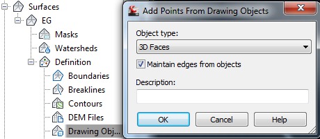
There is also a chance that you will want to add points to your surface that may not be in your drawing yet but are in an external point file. Go back to the Prospector. Under the surface EG, right-click the definition of Point Files and select Add. Click the plus (+) sign in the Add Point file dialog box, and then browse to and select the point file EG Add Points.txt. This file is in a PNEZD format. In the Specify Point File Format area, browse to and select the PNEZD comma delimited option. Lastly, deselect any advanced options and finally select OK. The points are added to your surface. To update the surface now, right-click EG and select Rebuild. The surface rebuilds with the new point file information.
Many of the ways to add information into a surface can be easily discovered by right-clicking the option and selecting Add. Civil 3D gives you several ways to create a surface and populate that surface with data.

Creating Associative Surfaces

Associative surfaces automatically adjust to changes made to other, related objects.

When surface associativity is on, surfaces are created with a relationship to the surface or profiles that created them.
Associativity allows you to:
  • Reshape the generating profiles to automatically reshape the surface.
  • Work with a group of surfaces as if they were one object. Just as reshaping one face of a solid box adjusts the entire box, reshaping one surface or edge in a group of associated surfaces adjusts the entire group.
  • Use geometric constraints on the 2D profiles of a surface.
  • Assign mathematical expressions to derive properties of surfaces, such as height and radius. For example, specify that the height of an extruded surface be equal to one half the length of another object.
As you add and edit objects, all objects become related and create a chain of dependency. Editing one object can affect all associated objects. It is important to understand the chain of associativity because moving or deleting one of the links in the chain can break the relationship between all the objects.
Note: To modify the shape of a surface that is generated from a curve or spline, you must select and modify the generating curve or spline, not the surface itself. If you modify the surface itself, you will lose associativity.
When associativity is on, the DELOBJ system variable is ignored. If Surface Associativity and NURBS Creation are both on, surfaces are created as NURBS surfaces, not associative surfaces.
Save time by planning your model ahead; you cannot go back and add associativity after the model has been created. Also, be careful not to accidentally break associativity by dragging objects away from the group.

Monday, June 17, 2019

To Find Serial Numbers & Product Keys

Serial Number Locations

Serial numbers are unique codes associated with your Autodesk Account and a particular product that you have purchased or is otherwise available to you. For 2014 versions and later, you can find them in Autodesk Account, on the Management tab. Depending on your license type, you may not need a serial number to launch your product.

Autodesk Account

The Management tab of your Autodesk Account page stores the serial numbers and product keys for each licensed product.
Image of Serial Number in Autodesk Account.
Note about serial number visibility in Autodesk Account: Only account administrators, such as Contract Managers and Software Coordinators, and Named Users with assigned software benefits will see serial numbers in Autodesk Account. You are the account administrator if you purchased a software subscription using your Autodesk Account or were assigned the role of Contract Manager or Software Coordinator by your company. If you do not see the software you wish to activate in your Autodesk account or see the message "Contact your admin for serial numbers," you need to contact the account administrator. Only an administrator can assign you as a Named User or End User and give you permissions to download and activate the software.

Education Community

When students, educators, and educational institutions download products from the Education Community, the product serial numbers are found in the following locations:
  • Displayed at the time of download
  • Sent by email
  • On the Management tab in Autodesk Account

Physical Media

Serial Numbers do not appear on software packaging for Autodesk software versions 2014 and newer. Serial numbers for these versions are emailed to you after you place an order or can be found in Autodesk Account.
If you have physical media (a DVD or USB key) for a 2013 or earlier product, your serial number and product key will be printed on the label of the product packaging.
 
Example of label from 2011 version. Format is similar for 2010 - 2013 product releases.

Product Key Locations

Product keys are codes that identify each product version. 
  • You can find product keys for recent versions of your product in Autodesk Account, on the Management tab. 
    Image of product key in Autodesk Account for serial number activation.
  • To look up a product key for a particular product version (2010 and later).

Older product keys

If you can't find the product key for older versions of Autodesk software (2013 and later), you may be able to find it in a text file in the installation folder.
To determine if your product key is available in your installation folder:
  1. Using your installation media, (USB key, DVD, download folder, etc.) navigate to the folder that contains the setup.exe file for your Autodesk product.
  2. In that folder, look for a file named MID.txtMID01.txtMID02.txt or some variation on that name.
  3. Open this file in Notepad and verify that the product name is correct.
  4. The first five characters of the part number should also be the product key for that product.


Example:

MID: Autodesk_Design_Suite_Ultimate_2012_64bit_SWL_ENU_C009_EXE1
Product Name: Autodesk Design Suite Ultimate 2012
Platform: Windows XP/Vista/Win7
Media: ESD
Part Number: 769D1-05Y001-P503E, 769D1-05Y001-P504E

Exercise 3: Importing Points from a Database

In this exercise, you will import points from a database to a drawing that uses description keys to sort points into groups.

This exercise continues from Exercise 2: Creating Point Groups.
Import points from a database
    Note:
    This exercise uses Points-1.dwg with the modifications you made in the previous exercise, or you can open Points-1a.dwg.
  1. In Toolspace, on the Prospector tab, right-click Points. Click Create.
  2. In the Create Points dialog box, click . Expand the Default Layer parameter, then change the value to V-NODE.
  3. In the Create Points dialog box, click Import Points.
  4. In the Format list, select External Project Point Database.
  5. Click . Select points.mdb. Click Open.
  6. In the Import Points dialog box, clear the Advanced Options check boxes.
  7. Click OK.
    The points are imported.
  8. In Toolspace, on the Prospector tab, right-click the _All Points point group. Click Zoom To.
    The points are displayed both in the drawing and in tabular form in the Toolspace list view. In the drawing window, if you move the cursor over a point, a tooltip displays basic data about the point. Notice that the two stormwater point groups appear to be empty. This is because they have not been updated with their new content. In the next few steps, you will see how Autodesk Civil 3D provides several ways to check the point data before adding it to your drawing.
Update point groups
  1. Right-click the Point Groups collection. Click Properties.
    The Point Groups dialog box is displayed. Point groups are listed here according to their display order, with the highest priority group at the top. Arrows at the side of the dialog box allow you to change the display order. The icon  indicates that an update is pending for a point group.
  2. To show the contents of the update for each point group, click . Review the list of points that the application is prepared to add to the Storm Manholes and Detention Pond point groups.
  3. In the Point Group Changes dialog box, click Close.
  4. To update the point groups, click . Click OK.
    Alternatively, you can right-click the Point Groups collection and click Update.
    The point groups update. Now, you can display their points in the list view and zoom to them in the drawing.
  5. Right-click a point group. Click Edit Points.
    The points are displayed in the Point Editor table. Review and change their attributes.

Exercise 2: Creating Point Groups

In this exercise, you will create point groups to sort the points as they are imported into a drawing.

This exercise continues from Exercise 1: Creating Description Keys.
Create point groups
    Note:
    This exercise uses Points-1.dwg with the modifications you made in the previous exercise.
  1. In Toolspace, on the Prospector tab, right-click the Point Groups collection. Click New.
  2. In the Point Group Properties dialog box, on the Information tab, in the Name field, enter Detention Pond. Optionally, enter a short description in the Description field.
  3. On the Raw Desc Matching tab, select POND*. Click Apply.
    This option specifies that all points with the POND* raw description are added to the Detention Pond point group.
    Notice how the description key setting is recorded on both the Include and Query Builder tabs. If you know SQL, you can see how you could add more criteria to the Query Builder tab to select a more specific set of points for the point group.
  4. Click OK.
  5. Create another point group by repeating Steps 1 through 4, but use the following parameters:
    NameStorm Manholes
    Raw Desc MatchingMHST*
    Your drawing should now contain the same description keys and point groups shown in sample drawing Points-1a.dwg.
    Note:
    The _All Points point group is created automatically. A point can belong to other point groups in the drawing, but it is always a member of the _All Points point group.
Change the point group label style
  1. In Toolspace, on the Prospector tab, expand the Point Groups collection.
  2. Right-click the _All Points collection. Click Properties.
  3. In the Point Group Properties dialog box, on the Information tab, change the Point Label Style to Standard.
  4. Click OK to close the Point Group Properties dialog box.