How to Add a curb subassembly
Add a curb subassembly
- In the Tool Palettes window, on the Curbs tab, click
 UrbanCurbGutterGeneral.
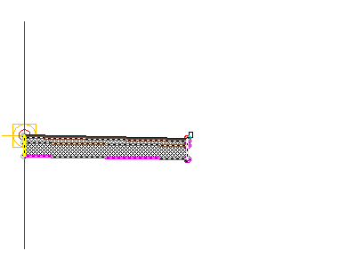
 - In the drawing, click the marker point at the top-right edge of the travel lane.
 Note:
Note:
If you attach the subassembly to the wrong marker, you can move it to the correct location. Press Esc to exit subassembly placement mode. Select the subassembly you wish to move. A blue grip is displayed when the subassembly is selected. Select the grip, and then click the correct marker point.
Add a sidewalk subassembly
- In the Tool Palettes window, on the Basic tab, click
 Basic Sidewalk.
 - In the Properties palette, under ADVANCED, specify the following parameters:
- Side: Right
- Width: 1.5
- Buffer Width 1: 0.5
- Buffer Width 2: 0.5
- In the drawing, click the marker point at the top, back of the curb.

Add a daylight subassembly
- In the Tool Palettes window, on the Basic tab, click
 BasicSideSlopeCutDitch.
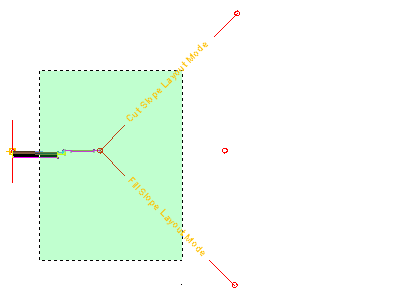
 - In the Properties palette, under ADVANCED, specify the following parameters:
- Side: Right
- Cut Slope: 2.000:1
- Fill Slope: 4.000:1
- In the drawing, click the marker point at the outside edge of the sidewalk subassembly.

- Press Esc.This action ends the subassembly placement command.
Mirror the subassemblies to the left of the baseline
- In the drawing, select the four subassemblies you added.
- Right click. Click Mirror.
- Click the marker point on the assembly baseline.The subassemblies are displayed on the left side of the assembly marker. The Mirrorcommand creates a mirror image of the selected subassemblies. All the subassembly parameters, except for the Side parameter, are retained.
 Note:
Note:
posted by Feature and Technology @ July 10, 2017
3 Comments
![]()


