How to Create Roundabout (Circulatory Road Dialog Box)
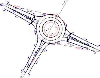
Use this dialog box to specify details for the circulatory road that comprises the center portion of the roundabout.
Note: This functionality has been replaced by the new roundabout feature and is included here for compatibility reasons. For current roundabouts, see About Roundabouts.
This dialog box is the first in a series of four dialog boxes that step you through creating a roundabout.
Roundabout Center Point
Specifies the X Y location of the center point of the roundabout. The location selected at the Specify roundabout center point prompt is displayed. You can change these values using the X and Y value fields, or by clicking the  and then selecting a location in the drawing.
Drawing Standard
Specifies the roundabout drawing standard used to create the roundabout.
- Roundabout Design Standard File
- Specifies the .xml file that is used to control some design and geometry aspects of this roundabout, according to geographical or organizational standards. If the current drawing is imperial, then the default location for this .xml file is the C:\ProgramData\Autodesk\C3D <version>\enu\Data\Corridor Design Standards\Imperial folder. If the current drawing is metric, the default location for this .xml file is the C:\ProgramData\Autodesk\C3D <version>\enu\Data\Corridor Design Standards\Metric folder. A Roundabout Design Standard File .xml file can contain more than one design standard or roundabout types; for example, one .xml file could contain a US standard, a Florida Standard, UK, France, and so on. The default roundabout design standard file is named Autodesk Civil 3D (Imperial or Metric) Roundabouts Presets.xml.
- Select Roundabout Standard
- Because a roundabout design standard file can contain more than one design standard, or roundabout types, you must use the Select Roundabout Standard option to select the desired roundabout design standard to apply.
Predefined Parameters To Import
You can select a set of parameters from the dropdown list. As soon as you select a set of parameters, the Roundabout Parameters and Markings Parameters are updated with the selected values. If desired, you can change the value of any parameter.
To add a new set of parameters to the list, click  . The Preset - Add dialog box is displayed.
Enter a preset name for the new set of parameters, and then enter the values for all parameters. If you want to edit existing sets of predefined parameters, select the preset that you want to edit from the list of presets and click  . To delete a set of predefined parameters, select the preset that you want to delete and click
  . You can only delete user-defined presets (ones that you or someone else has created). You cannot delete the default presets.
Roundabout Parameters
These parameters specify the location and geometry of the central area components of the roundabout.
Hovering the cursor over these controls displays a conceptual illustration of the component or geometry specified by that control on the right side of this dialog box.
- Outer Radius
- Specifies the outer radius of the roundabout driving area.
- Circulatory Road Width
- When the US_Imperial roundabout drawing standard is selected, this parameter is displayed. It specifies the width of the roundabout driving area. (French standard)– defines the inner radius of the roundabout driving area (outer radius of the traversable strip).
- Apron Width
- When the US_Imperial roundabout drawing standard is selected, this parameter is displayed. It specifies the apron strip width.
- Inner Radius
- When the French (SETRA) roundabout drawing standard is selected, this parameter is displayed. It specifies the inner radius of the roundabout driving area (outer radius of the traversable strip).
- Traversable Extra Width
- When the French (SETRA) roundabout drawing standard is selected, this parameter is displayed. It specifies an extra width for the traversable area of the central area.
Markings Parameters
These parameters specify the markings for the central area components of the roundabout.
Hovering the cursor over these controls displays a conceptual illustration of the component or geometry specified by that control on the right side of this dialog box.
- Outer Offset
- Specifies the distance of the outer radius marking from the outer edge of a roundabout.
- Number of Lanes To Mark
- Specifies the number of driving lanes.
- Inner Offset
- Specifies the distance of the inner radius marking from traversable area of a roundabout.
- Lane Marker Line Width
- Specifies the width of the inner and outer radius marking.
- Lane Marker Linetype
- Specifies the marker line linetype.
Site
Specifies the site to which the roundabout will be added. Site also controls the site parameters of all approaches connected to this roundabout.
Alignment Style
Specifies the alignment style from the list of styles available in the drawing.
Alignment Layer
Specifies the alignment layer from the list of layers available in the drawing.
Alignment Name Prefix
Displays the name of the alignment used to specify the central approach road. This name is used as a prefix for the alignments that are generated by the roundabout creation. For the right edge alignment, the suffix “_EDGE_RIGHT” will be added to the alignment name. For the left edge alignment, the suffix “_EDGE_LEFT” will be added to this name.
Alignment Label Set
Specifies the alignment label set from the list of label sets available in the drawing.


0 Comments:
Post a Comment
Subscribe to Post Comments [Atom]
<< Home