Saturday, May 18, 2019

Rotating Objects

You can rotate objects in your drawing around a specified base point.

To determine the angle of rotation, you can enter an angle value, drag using the cursor, or specify a reference angle to align to an absolute angle.

Rotate an Object by a Specified Angle

Enter a rotation angle value from 0 to 360 degrees. You can also enter values in radians, grads, or surveyor bearings. Entering a positive angle value rotates the objects counterclockwise or clockwise, depending on the base angle direction setting in the Drawing Units dialog box.

Rotate an Object by Dragging

Drag the object around the base point and specify a second point. Use Ortho mode, polar tracking, or object snaps for greater precision.
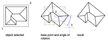
For example, you can rotate the plan view of a house by selecting the objects (1), specifying a base point (2), and specifying an angle of rotation by dragging to another point (3).
Rotate an Object to an Absolute Angle

With the Reference option, you can rotate an object to align it to an absolute angle.
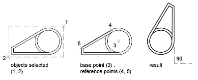
For example, to rotate the part in the illustration so the diagonal edge rotates to 90 degrees, you select the objects to be rotated (1, 2), specify the base point (3), and enter the Reference option. For the reference angle, specify the two endpoints of the diagonal line (4, 5). For the new angle, enter 90.
Rotate an Object in 3D

To rotate 3D objects, you can use either ROTATE or ROTATE3D.
  • With ROTATE, you can rotate objects around a specified base point. The axis of rotation passes through the base point and is parallel to the Z axis of the current UCS.
  • With ROTATE3D, you can specify the axis of rotation using either two points; an object; the XY, or Z axis; or the Z direction of the current view.
  • Note: The ROTATE3D command is not available in AutoCAD LT.

Labels:

Friday, May 17, 2019

Rotate an object based on an existing angle


You can rotate an object based on a known angle or the angle of two points you select. In the following example, you want to rotate the chair and desk on the right to match the chair and table on the left. The new angle is unknown.

Rotate - Original Position
  1. At the Command prompt, enter rotate.
  2. At the Command prompt to Select objects: Select the objects to rotate.
  3. At the Command prompt to Specify base point: In the object to rotate, select the appropriate base point.
    (In the following example, the base point is the midpoint of the back of the chair. All selected objects rotate around that base point.)
Select Base or Rotation point


  1. At the Command prompt to Specify rotation angle or [Copy/Reference] <0>: R
Note: The reference option refers to the current angle of the object to rotate. If you know the angle, known, enter that value. For unknown angles, enter R (as shown previously) to select a reference angle.
  1. At the Command prompt to Specify the reference angle <0>: Enter a known angle, or select a first and second point to specify the existing angle.
Existing angle based on two points
  1. At the Command prompt to Specify the new angle or [Points] <0>: P
  2. Select the starting point of the new angle, and then select the endpoint. The first object is rotated to match the angle of the second object.
Select Points to provide new angle

Labels:

Thursday, May 16, 2019

Edit the Geographic Location

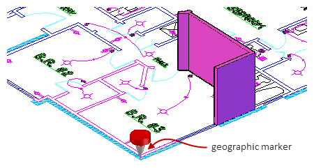
You can change all properties of the geographic marker as well as the GIS coordinate system assigned to the drawing file.

  1. Click Geolocation tabLocation panelEdit Location drop-downFrom Map Find
  2. If the Geolocation - Online Map Data task dialog box displays, click Yes.
  3. To change the geographic location the geographic marker points to:
    1. Zoom the map such that the marker and the location to set are clearly visible.
    2. Drag the marker to the desired location.
      Tip: If the marker and locations to set are too far apart, zoom only to the location to set, right-click and select Move Marker Here.
  4. Click Next.
  5. To change the GIS coordinate System:
    1. From the GIS coordinate system list, select the desired coordinate system.
    2. In the Drawing Unit box, specify the linear measurement of a drawing unit.
  6. Click Continue.
  7. To change the position of the geographic marker in model space click the corresponding position. If not, press ENTER.
  8. To change the north direction, specify the angle from the X axis to the north direction. If not press ENTER.

Labels:

Setting Geographic Location

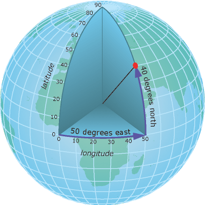
Inserting geographic location information to a drawing file makes points within the drawing correspond to geographic locations on the surface of the Earth.
Geographic location information in a drawing file is built around an entity known as the geographic marker. The geographic marker points to a reference point in model space that corresponds to a location on the surface of the earth of known latitude and longitude. The program also captures the direction of the north at this location. Based on this information the program can derive the geographic coordinates of all other points in the drawing file.
Typically a geographic location is defined by its coordinates (for example, latitude, longitude, and elevation) and the coordinate system (for example, WGS 84) used to define the coordinates. Moreover, the coordinates of a location can differ from one GIS coordinate system to another. Hence, when you specify the geographic location of the geographic marker, the system also captures the details of the GIS coordinate system.
Typically CAD drawings are unitless and are drawn at 1:1 scale. You are free to decide the linear unit a drawing unit represents. GIS systems, on the other hand, allow the coordinate system to decide the linear units. In order to map CAD coordinates to GIS coordinates, the system needs to interpret CAD drawing units in terms of linear units. The system uses the setting stored in the INSUNITS system variable as the default linear measurement of a drawing unit. However, when you insert geographic location information, you have the option of specifying a different linear measurement (for a drawing unit).
After you insert a geographic marker in a drawing, you can:
  • Make the program automatically determine the angle of sunlight when you perform sun and sky simulation (photometric studies).
  • Insert a map from an online maps service in a viewport.
  • Perform environment studies.
  • Use position markers to mark geographic locations and record related notes.
  • Locate yourself on the map in real-time on systems that support location sensing.
  • Export to AutoCAD Map 3D, and expect the model to position itself automatically.
  • Import raster files that contain geographic location information and expect them to position themselves automatically (This requires AutoCAD Raster Design).
Note: The geographic marker cannot be selected, but you can control its visibility using the GEOMARKERVISIBILITY system variable.
You can remove geographic location information from a drawing file using the GEOREMOVE command. The geographic marker and GIS coordinate system are removed from the drawing file. However, position markers continue to remain in the drawing file.

Labels:

GIS Coordinate Systems

Coordinate systems typically used in Geographical Information Systems (GIS) are referred to as GIS coordinate systems.
CAD coordinate systems such as UCS and WCS describe points relative to the object being modeled, not relative to a location on the surface of the Earth. GIS coordinate systems, on the other hand, describe locations on the surface of the earth. GIS coordinate systems handle significantly larger scales than CAD coordinate systems and deal with issues such as the curvature of the earth and terrain, which are insignificant to CAD coordinate systems.
There are two types of GIS coordinates systems that are commonly used. They are geographic coordinate systems and projected coordinate systems.

Geographic Coordinate Systems

Geographic coordinate systems take into account the curvature of the earth and a location is commonly specified in terms of longitude, latitude and elevation.
Because the earth is not perfectly round, no single geographic coordinate system is able to accurately define all locations on the surface of the Earth. Consequently, various organizations define local coordinate systems, where measurements are taken locally from a local datum.

Local coordinate systems are considered more accurate because they align more closely with the Earth's surface in that locality, in comparison to an Earth-centric datum. Often, more than one coordinate system may cover the location you are interested in. As a general rule of thumb, the coordinate system with its datum closest to that location is considered to be the most accurate.

Projected Coordinate Systems

Projected Coordinate Systems use a mathematical transformation to convert geographic coordinate systems into a flat 2D representation. They use linear measurements for coordinates. As such they make it possible to transform GIS coordinates to CAD coordinates.

Mapping CAD Coordinates to GIS Coordinates

When you assign geographic location information to a drawing file (GEOGRAPHICLOCATION command), you also assign a projected coordinate system to the drawing.
Typically CAD drawings are unitless and are drawn at 1:1 scale. You are free to decide the linear unit a drawing unit represents. GIS systems, on the other hand, allow the coordinate system to decide the linear units. In order to map CAD coordinates to GIS coordinates, the system needs to interpret CAD drawing units in terms of linear units. The system uses the setting stored in the INSUNITS system variable as the default linear measurement of a drawing unit. However, when you insert geographic location information, you have the option of specifying a different linear measurement (for a drawing unit).

Labels:

Wednesday, May 15, 2019

Orbit the View of a 3D Object

  1. Select one or more objects that you want to view with 3DORBIT or select no objects if you want to view the entire drawing.
    Note: OLE objects and raster objects do not appear in the 3D Orbit view.
  2. Click View tab  Navigate panel  Orbit drop-down  Orbit Find
  3. Use one of the following methods to orbit around the objects:
    • To rotate along the XY plane, click in the drawing and drag the cursor left or right.
    • To rotate along the Z axis, click in the drawing and drag the cursor up or down.
    • To allow unconstrained orbiting along the XY plane and the Z axis, press Shift while you drag the cursor. An arcball is displayed and you can use the 3D Free Orbit interaction.

To Orbit a 3D View Without Constraining the Direction (3D Free Orbit)

  1. Select one or more objects that you want to view with 3DFORBIT or select no objects if you want to view the entire drawing.
  2. Click View tab  Navigate panel  Orbit drop-down  Free Orbit Find
  3. An arcball is displayed in the drawing area.
  4. To set the target point of the orbit, right-click the drawing area and choose an option.
    • To orbit the objects about the center point of the arc ball, select Enable Orbit Auto Target.
    • To orbit the camera location, or point of view around the objects, clear the Enable Orbit Auto Target checkmark. The center of the arcball becomes the target point.
  5. Move the cursor over different parts of the arcball to display the 3D free orbit icon that you want to use. Then drag to orbit the view.

Labels:

Exercise 5: Working with Roundabout Design Standards and Presets

In this exercise, you save a group of geometric parameters as a preset that can be quickly applied to a roundabout.

Presets are saved in a design standards file, the contents of which you will examine at the end of this exercise.
Select a a baseline roundabout
  1. Open Roundabout-Preset.dwg..
  2. Click Modify tab Design panel Intersection  Find.
  3. Click Intersection tab Modify Roundabout panel Edit Roundabout  Find.
  4. Click the Roundabout_ISLAND alignment.
Specify circulatory road presets
  1. In the Create Roundabout - Circulatory Road dialog box, under Predefined Parameters to Import, click .
  2. In the Preset - Add dialog box, under Preset Name, enter R = 40.
  3. Under Roundabout Parameters, enter the following parameters:
    • Outer Radius40
    • Circulatory Road Width10
    • Apron Width3
  4. Under Markings Parameters, enter the following parameters:
    • Outer Offset0.5
    • Inner Offset0.5
    • Marker Line Width0.3
    • Number of Lanes to Mark3
    • Lane Marker Width0.2
    • Lane Marker LinetypeDASHED
  5. Click OK.
    Note:
    In the Create Roundabout - Circulatory Road dialog box, under Drawing Standard, the Roundabout Drawing Standard File is the xml file in which the presets are stored. You will examine the contents of this file at the end of this exercise.
  6. At the bottom of the dialog box, click Next.
Specify approach road presets
  1. In the Create Roundabout - Approach Roads dialog box, under Predefined Parameters to Import, click .
  2. In the Preset - Add dialog box, under Preset Name, enter R = 40.
  3. Under Approach Road Parameters, enter the following parameters:
    • Exit Road Width5
    • Exit Radius25
    • Exit Flare Length80
    • Exit Flare TypeLine
    • Width at Departure4.5
    • Entry Road Width4.5
    • Entry Radius20
    • Entry Flare Length80
    • Entry Flare TypeLine
    • Width at Approach4.25
  4. Click OK.
  5. In the Create Roundabout - Approach Roads dialog box, click Apply to All.
  6. At the bottom of the dialog box, click Next.
Specify island presets
  1. In the Create Roundabout - Islands dialog box, under Predefined Parameters to Import, click .
  2. In the Preset - Add dialog box, under Preset Name, enter R = 40.
  3. Under Construction Triangle Parameters, enter the following parameters:
    • Length60
    • Base4.5
  4. Under Splitter Island Parameters, enter the following parameters:
    • Provide Crosswalk (Length): 3
    • Rounding at Exit1
    • Offset from Circle at Exit1
    • Offset at Exit0.5
    • Offset at Departure0.3
    • Rounding at Tip0.25
    • Island Total Length15
    • Island Base Length8
    • Rounding at Entry1
    • Offset from Circle at Entry0.5
    • Offset at Entry0.5
    • Offset at Approach1
    • Rounding at Crosswalk0.5
  5. Click OK.
  6. In the Create Roundabout - Islands dialog box, click Apply to All.
  7. At the bottom of the dialog box, click Next. Click Finish.
    The roundabout is updated to reflect the parameters that you defined for the preset. When you create another roundabout, the presets that you defined will be available.
Examine the roundabout design standards file
  1. Open the Autodesk Civil 3D Metric Roundabouts Presets.xml with your default Internet browser.
  2. Under RoundaboutPresets StandardPresets US standardType=”EN-US”, examine the contents of the following blocks:
    • RoundaboutPreset name=”R = 40”
    • ApproachPreset name=”R = 40”
    • IslandsPreset name=”R = 40”
    These blocks contain the parameters you entered earlier in this exercise. If you are familiar with XML code, you can edit this file directly to add presets without using the Preset - Add dialog box in AutoCAD Civil 3D.
  3. Close Windows Explorer and your Internet browser.
Edit a preset
  1. Click Intersection tab Modify Roundabout panel Edit Roundabout  Find.
  2. Click the Approach_SN alignment.
  3. In the Create Roundabout - Approach Roads dialog box, under Predefined Parameters to Import, select R = 40. Click .
  4. In the Preset - Edit dialog box, under Approach Road Parameters, change the following parameters:
    • Entry Road Width9
    • Entry Flare TypeArc
  5. Click OK.
  6. At the top of the Create Roundabout - Approach Roads dialog box, use the drop-down list to select South to North Approach (1).
  7. Under Predefined Parameters to Import, select R = 40.
  8. At the bottom of the dialog box, click Next twice. Click Finish.
    The approach roads to the north and south of the roundabout are updated to reflect the updated preset. The other approach roads were not affected because you did not apply the new preset to them.
Delete a preset
  1. Click Intersection tab Modify Roundabout panel Edit Roundabout  Find.
  2. Click the Approach_SN alignment.
  3. In the Create Roundabout - Approach Roads dialog box, under Predefined Parameters to Import, select R = 40. Click .
    The preset is removed from the list.
  4. Under Predefined Parameters to Import, select RG = 12. Click .
    The preset cannot be deleted because it was shipped with AutoCAD Civil 3D. Only user-defined presets may be edited or deleted.
  5. Click OK.
  6. In the Create Roundabout - Approach Roads dialog box, click Cancel.

Labels: