Tuesday, November 27, 2018

Construction Lines

Construction lines (also known as xlines) are temporary linework entities that can be used as references when creating and positioning other objects or linework. For example, you can use construction lines to prepare multiple views of the same item, or create temporary intersections to serve as object snaps.
Construction lines are either circles or straight lines that extend to infinity in both directions. In either case, they do not change the total area of the drawing and have no effect on zooming or viewports. You can move, rotate, copy, or delete construction lines just like other objects.
The regular AutoCAD construction line functionality is still available via the XLINE command. However, the AutoCAD Architecture construction line feature is designed to give you a more intuitive way of drawing construction lines based on the geometry of existing objects or linework. No command line entry is required.
In most cases, you would probably want to draw construction lines based on segments of existing objects, but you can also draw them by specifying any two points in the drawing area, without regard to existing objects or linework.

How To Use a Custom Arrowhead

How to create user designed arrows with the Dimension Style Manager.
  1. Click Home tabAnnotation panelDimension Style Find
  2. In the Dimension Style Manager, select the style you want to change. Click Modify.
  3. In the Dimension Style Manager, Symbols and Arrows tab, under Arrowheads, select User Arrow from the First arrowhead list.
  4. In the Select Custom Arrow Block dialog box, enter the name of the block that you want to use as an arrowhead. Click OK.
  5. To choose a different custom arrowhead for the second arrowhead, repeat steps 3 and 4, choosing User Arrow from the Second arrowhead list (optional).
  6. Click OK.
  7. Click Close to exit the Dimension Style Manager.

Low quality in geometry when opening 3D dwg file from C3D

Issue:

When watching an Autodesk® AutoCAD® Civil 3D® 3D DWG in the A360 Online Viewer the geometry of 3D solids appear degraded and of low quality.

Causes:

The A360 Viewer is not (yet) designed to work with Coordinate Systems. 
If the 3D solid geometry is very for from the origin (X,Y = 0,0) the geometry display gets degraded.

Solution:

  • Before uploading a georeferenced DWG to the A360 Viewer, move all objects as close as possible to X,Y = 0,0

Saturday, November 24, 2018

How To Edit Layer Key Styles - AutoCAD Civil 3D

Use this procedure to edit a layer key style.
  • You can change the layer standard that a layer key style is based on, or you can specify a layer standard for a nonstandard layer key style.
  • You can add layer keys to the layer key style.
  • You can remove any layer keys except the default layer keys.
  • You can edit the layer properties of the layers to which the layer keys map.
  • You can specify whether layer key overrides can be used with the layer key style.
  1. Click Home tabLayers panelLayer Key Styles. Alternatively, you can click  in the Layer Properties Manager.
    The Style Manager is displayed with the current drawing expanded in the tree view.
  2. Select the layer key style that you want to change.
  3. Click the Keys tab.
  4. Specify the layer standard:
    If you want to…Then…
    specify a different layer standard on which to base the layer key styleselect a new layer standard for Standard.
    specify that the layer key style is not based on a layer standardselect Non Standard for Standard.
    Note: You can base more than one layer key style on the same layer standard so that each layer key style can be used with different color, linetype, and override settings.
  5. To add a new layer key, click Add.
    New keys are added with default values.
  6. To delete a layer key, select a layer key, and click Remove.
    You cannot delete the default layer keys.
    Tip: To change the properties of more than one layer key at a time, hold down Ctrl and select the additional layer keys.
  7. Select a layer key, and specify the layer key properties:
    If you want to…Then…
    modify the description for a layer keydouble-click the text that you want to change for Description, and enter new text.
    modify the layer nameunder Layer, click the [...] button. Specify the appropriate values for layer fields, and click OK.
    modify the color for a layer keyunder Color, click the current value. Select a new color, and click OK.
    modify the linetype for a layer keyunder Linetype, click the current value. Select a new linetype, and click OK.
    modify the lineweight for a layer keyunder Lineweight, click the current value. Select a new lineweight, and click OK.
    specify whether a layer key will plotunder Plot, click the printer icon to turn plotting on or off.
    specify whether to allow layer field overridesunder Allow Overrides, clear the options for which overrides are not allowed.
    Tip: When you first add a new layer key by default the name generated for the layer is not yet based on the layer standard used. This is why the layer overrides are inactive. Modify first the layer name associated to the key by clicking the [...] button. Once the name is based on the layer standard, you can allow overrides to the standard.
  8. Click OK.

Modify the scale of specific linetypes in AutoCAD

Issue:

There may be a need to scale individual linetypes in a drawing so that they appear smaller or larger depending on the need. Changing the LTSCALE will modify all linetype scales in the drawing, so how can one be selective and scale one or more linetypes?

Solution:

The solution is to select the linetype and then modify the scale in the Properties palette. In Properties, when no objects are selected the Linetype Scale field under the General category will scale linetypes globally in the drawing. To only scale select linetypes, select one or more existing line entities in the drawing and then change the Linetype Scale in the Properties palette. 

Center a Railing Using Modify Tools

Use this procedure to center a railing on a specified axis or between any two specified points.
  1. Select the railing to center.
  2. Click Railing tabModify panelCenter
  3. Select an existing axis line on which to center the railing, or press Enter and then specify two points between which to center the railing.

How To Modify Support File Search Paths

You can modify the file paths and folder locations of the support files used by the product.

To Add a Path to the Support File Search Paths

  1. Click the Application menu  Options.
  2. In the Options dialog box, Files tab, select Support File Search Path.
  3. Click Add.
  4. Click Browse.
  5. In the Browse for Folder dialog box, browse to and select the folder to add. Click OK.
  6. In the Options dialog box, click OK.

To Override all Support File Search Paths Using a Command Line Switch

  1. Right-click the program icon on the Windows desktop (or Start menu on Windows 7 and earlier), and click Properties.
  2. In the product's Properties dialog box, Shortcut tab, in the Target box, append the /s command line switch and the paths you want to use with the following syntax:
    "drive:\pathname\product.exe" ["drawing name"] /s "support_path1;support_path2"
    For example, append
    /s "c:\AcadJobs;c:\AcadJobs\Support"
  3. Click OK.

Monday, November 19, 2018

How to save an AutoCAD drawing to a previous or older file format

Issue:

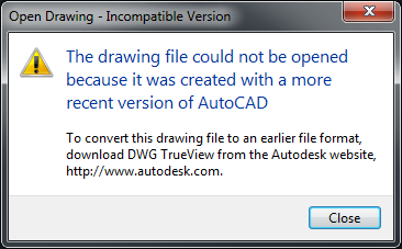
How to save a drawing in AutoCAD to an older file format to allow prior versions of AutoCAD to open the file instead of receiving the following message: 
 
Open Drawing - Incompatible Version
The drawing file could not be opened because it was created with a more recent version of AutoCAD.
 

User-added image

Causes:

The file was created or saved in a more recent version of AutoCAD in a newer DWG format. See the article  AutoCAD drawing file formats for the AutoCAD file format change history and compatibilities.

Solution:

The Save As dialog window in AutoCAD allows selecting different drawing versions:
  1. Click the "Save As" button on the Quick Access Toolbar in AutoCAD or type SAVEAS on the command line.
  2. It is suggested to change the name of the file to prevent overwriting the original.
  3. Choose the appropriate file format version under the "Files of Type" drop-down menu.
  4. Save the file.
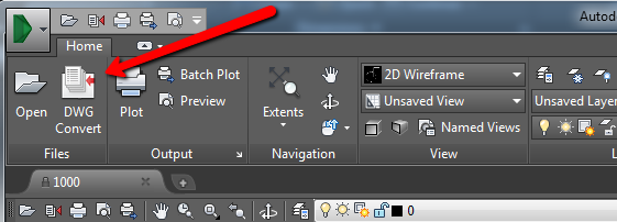
If a file has been received in a newer format that cannot be opened by the version of AutoCAD currently installed (hence receiving the above "incompatible version message"), ask the sender to resave it to the older format that can be used or download and install the latest version of  DWG TrueView (free Autodesk file viewing software) and use its DWG Convert feature to convert the drawing:
  1. Create a copy of the drawing file to be converted.
  2. Launch DWG TrueView.
  3. Click the application menu in the upper-left and choose DWG Convert (or pick it on the ribbon if you have a file open).User-added image
  4. Add the file(s) in the Files Tree list (click the green plus Add Files button).
  5. Choose the appropriate file format version.
  6. Click Convert.
For AutoCAD for Mac, use AutoCAD Mobile (TrueView is not available for the Mac OS):
  1. Log in to AutoCAD Mobile.
  2. Upload the drawing and then view it.
  3. Click the "Download" button.
  4. Choose DWG and the appropriate file format version.

Enable or disable hardware acceleration in AutoCAD

Issue:

You want to turn video hardware acceleration on or off in AutoCAD to improve graphics performance.

Causes:

If you have a video card that supports OpenGL, you can improve graphics performance and productivity when working with 3D models by turning on hardware acceleration. This helps overall performance, not just with 3D work. 

However, some video cards and drivers that support OpenGL are not compatible with AutoCAD when hardware acceleration is turned on. This incompatibility may result in unexpected problems. To test for optimized working conditions in your environment, you can toggle hardware acceleration on and off.

Solution:

There are several ways to toggle hardware acceleration in AutoCAD-based products. Try one of the following methods:
  • Enter the GRAPHICSCONFIG command and click the Hardware Configuration button.
  • Enter the 3DCONFIG command and click the Hardware Configuration button.
  • Enter OPTIONS on the command line or choose it from the Application menu to open the Options dialog box. On the System tab, click the Graphics Performance button. Then click the Hardware Acceleration button to turn it off or on.
  • Click the GRAPHICSCONFIG performance button in the lower-right corner of the AutoCAD application window.
    User-added image
There may be a delay the first time you use GRAPHICSCONFIG or 3DCONFIG or when you click the performance button. 

Note: The interface options may differ, depending on product and product version. AutoCAD LT 2011 and earlier do not support hardware acceleration and do not have 3DCONFIG.

Was this helpful?

Install the CAD Manager Control Utility

Issue:

You would like to know how to install the CAD Manager Control Utility.

Solution:

  1. Run an Autodesk installer.
  2. Click Install Tools & Utilities.
  3. Check Autodesk CAD Manager Tools.
  4. Click Install.
The utility shows up under Start > All Programs > Autodesk > CAD Manager Tools.

How To Create a Model Space View

A model space view is a named view that represents a view definition in model space. You can create multiple model space views in a view drawing, each with its own name, description, layer settings, and drawing scale.
When a model space view is placed onto a sheet, its own viewport scale, layer settings, and the display configuration of the view drawing are used in the sheet view created. The view direction, however, defaults to plan.
You can associate an AutoCAD layer snapshot with a model space view. If you then place the model space view on a sheet, the AutoCAD layer snapshot determines the On/Off and Freeze/Thaw settings of the model space layers. The layer settings from the layer snapshot will only be used if the project has not been set up to synchronize view drawing layers with sheet view layers. If that synchronization has been set up, the layer settings from the view drawing’s model space are used, and any attached layer snapshots on the model space view are ignored.
Defining a model space view
Displaying a model space view
  1. On the Quick Access toolbar, click Project Navigator .
  2. On the Views tab, select the view drawing in which you want to create a model space view, right-click, and click Open.
  3. Select the view drawing again, right-click, and click New Model Space View.
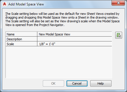
  4. In the Add Model Space View dialog box, enter a name for the new model space view.
  5. Define the settings for the new model space view:
    If you want to…Then…
    enter a description for the model space viewclick the setting for Description and add a description of the model space view.
    change the scale of the model space viewselect a scale from the list of those used in the current view drawing.
  6. Click  to define the boundaries of the new model space view.
  7. Specify the first boundary point of the desired view area.
  8. Specify the second boundary point of the desired view area.
  9. Click OK.
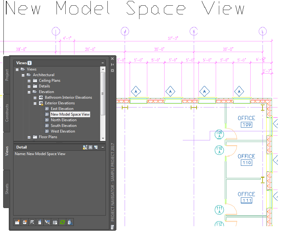
    The new model space view is listed under the view drawing from which it was created.
  10. To associate an AutoCAD layer snapshot with the new model space view, select the model space view in the Drawing Explorer, right-click, and click Save Layer State.
  11. Open the model space view using either of the following methods:
    • Double-click it in the Drawing Explorer.
    • Select the model space view in the Drawing Explorer, right-click, and click Open.

Change the Location of a Space Boundary in AutoCad Civil 3D

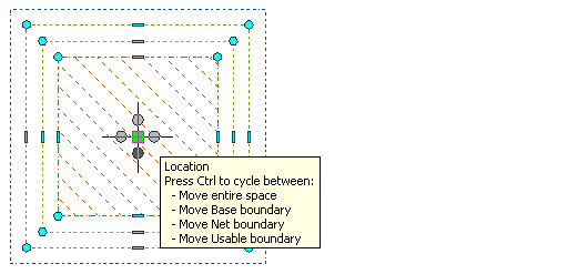
Use this procedure to move an individual space boundary to a different location with grips. You can move individual boundaries only if you have selected Manual for Offset boundaries.
For associative spaces, only the net, usable, and gross boundaries can be moved. The base boundary is tied to the boundary objects.
  1. Select the space for which you want to move an individual boundary.
  2. Move a boundary as necessary:
    If you want to…Then…
    move the entire spacemove space to the desired location and click to release it.
    move the base boundary of the spaceclick and hold the location grip, and press Ctrl to switch to Move base boundary mode. Then move the base boundary to the desired location, and click to release it.
    move the net boundary of the spaceclick and hold the location grip, and press Ctrl twice to switch to Move net boundary mode. Then move the net boundary to the desired location, and click to release it.
    move the usable boundary of the spaceclick and hold the location grip, and press Ctrl 3 times to switch to Move usable boundary mode. Then move the usable boundary to the desired location, and click to release it.
    move the gross boundary of the spaceclick and hold the location grip, and press Ctrl 4 times to switch to Move gross boundary mode. Then move the gross boundary to the desired location, and click to release it.

Wednesday, November 14, 2018

To Change the Space of an Object

When you create the geometry that is actually part of the model, you create it in model space. Then, you can switch to a layout tab that represents the sheet of paper on which you want to plot. You can then place model space viewports onto the layout and set the scale for each viewport.
Anything that is actually part of the model should be created in model space. Annotations that are only needed on the printed sheet are then typically created in paper space. But what happens if you accidentally create model geometry in paper space, or if you create annotations in model space? You can use the Change Space tool to move objects from model space to paper space, or from paper space to model space.
For example, in the Floor Plan view, suppose you inadvertently added the room labels while working in model space. When you switch to the Model tab, you can see those labels. The labels really should have been created in paper space, since they only need to appear in the layout. Switch back to the Furniture Plan layout. You can then use the Change Space tool to move those objects from model space to paper space.
First, double-click in the Floor Plan viewport to switch to model space. Notice that when you move the cursor over objects in this viewport, such as the walls or the labels, they highlight, because you are now working in model space inside the viewport and all of those objects are model space objects. Now, you are ready to move the text to paper space.
On the Home ribbon, expand the Modify panel and click the Change Space tool. The program prompts you to select objects. Click to select the three room labels. Then, right-click to complete the object selection. Next, the program prompts you to set the source viewport active and then press ENTER to continue. The source viewport determines the paper space location of the transferred objects. Since the source viewport is already the active viewport, simply press ENTER. The three text objects are immediately moved from model space to paper space. You can see that you are currently working in paper space by the presence of the paper space icon in the lower-left corner and the fact that the button in the Status bar shows the word "PAPER." And now, when you move the cursor over the labels, they highlight. When you move the cursor over the walls, however, they do not highlight, because they are in model space.
There is also a block representing a telephone that appears to have been drawn on the reception desk. However, even though you are currently working in paper space, when you move the cursor over the phone, it highlights. The phone was inadvertently inserted in paper space. When you switch to the Model tab, you do not see the phone. But since the phone should actually part of the model, it should have been created in model space.
Switch back to the Furniture Plan layout. Then, on the Home ribbon, expand the Modify panel and click the Change Space tool again. The program prompts you to select objects. Click to select the phone and then right-click to complete the object selection. This time, since you were working in paper space and the object you selected was a paper space object, the program prompts you to set the target viewport active and then press ENTER to continue. When transferring objects to model space, the target viewport that you click determines the model space location of the transferred objects. Click in the Reception Desk viewport and then press ENTER. The object is immediately moved from paper space to model space and scaled by an appropriate scale factor so that its visual size remains unchanged.
Switch back to the Model tab, and now you can see that the phone has been moved to model space.

Friday, November 9, 2018

To Insert Dialog Box in AutoCAD

Specifies the name and position of the block or drawing to insert.
INSERT (Command)  Find
The position of the inserted block depends on the orientation of the UCS.

Name

Specifies the name of a block to insert, or the name of a file to insert as a block.
Browse
Opens the Select Drawing File dialog box (a standard file selection dialog box) where you can select a block or drawing file to insert.
Path
Specifies the path to the block.
Locate Using Geographic Data
Inserts drawing using geographic data as the reference.
Specifies if the current and attached drawing contain geographic data. This option is available only if both drawings have geographic data.
Description
Displays the description that was saved with the block.
Preview
Displays a preview of the specified block to insert. A lightning bolt icon in the lower-right corner of the preview indicates that the block is dynamic. A icon indicates that the block is annotative.

Insertion Point

Specifies the insertion point for the block.
Specify On-Screen
Specifies the insertion point of the block using the pointing device.
Input Coordinates
Allows you to manually enter the XY, and Z coordinate value for the insertion point of the block.
X
Sets the X coordinate value.
Y
Sets the Y coordinate value.
Z
Sets the Z coordinate value.

Scale

Specifies the scale for the inserted block. Specifying negative values for the XY, and Zscale factors inserts a mirror image of a block.
Specify On-Screen
Specifies the scale of the block using the pointing device.
Input Scale Factor
Allows you to manually enter a scale factor for the block.
X
Sets the X scale factor.
Y
Sets the Y scale factor.
Z
Sets the Z scale factor.
Uniform Scale
Specifies a single scale value for XY, and Z coordinates.

Rotation

Specifies the rotation angle for the inserted block in the current UCS.
Specify On-Screen
Specifies the rotation of the block using the pointing device.
Input Angle
Allows you to manually enter an angle of rotation for the block.
Angle
Sets a rotation angle for the inserted block.

Block Unit

Displays information about the block units.
Unit
Specifies the INSUNITS value for the inserted block.
Factor
Displays the unit scale factor, which is calculated based on the INSUNITS value of the block and the drawing units.

Explode

Explodes the block and inserts the individual parts of the block. When Explode is selected, you can specify a uniform scale factor only.
Component objects of a block drawn on layer 0 remain on that layer. Objects having color BYBLOCK are white. Objects with linetype BYBLOCK have the CONTINUOUS linetype.