Friday, December 7, 2018

How to select Objects using Lasso

Using a lasso to select objects
Selecting Objects Using a Lasso
You can also select objects using a lasso, an irregular shape that you drag around the objects. This method can be used whenever the program prompts you to select objects or to preselect objects when no command is active.
On the Home ribbon, in the Modify panel, click the Erase tool. The program prompts you to select objects. Click in a blank area of the drawing and then drag around the objects you want to select. Notice that as you drag, you can see the lasso border begin to form. If you begin moving the cursor to the right of where you clicked, you create a window lasso, so that only those objects that are entirely inside the lasso are selected. You can see that it is a window lasso because it has a solid border and a blue background. Also notice that objects become highlighted to indicate that they will be selected. When you release the mouse button, the lasso is completed. The selected objects are highlighted, and in the command line you can see the number of objects found.
Click and drag again, but this time begin moving the cursor to the left of where you clicked. Now you are creating a crossing lasso, so that objects that are entirely inside the lasso or crossing its border are selected. You can see that it is a crossing lasso because it has a dashed border and a green background. Again, notice that objects become highlighted to indicate that they will be selected. When you release the mouse button, the lasso is completed. The selected objects are highlighted, and in the command line you can see the number of objects found, how many of those were duplicates, and the total number of objects now in the selection set.
You do not have to remember to click and drag in the right direction to use a window or crossing lasso. Click and drag again, but this time, notice that in the command line, the program actually tells you whether you are currently using a window lasso or a crossing lasso, and it prompts you to Press Spacebar to cycle options. When you press the SPACEBAR, the program cycles from a window lasso, to a fence lasso, to a crossing lasso, and then back to a window lasso again. You have already seen the window lasso and crossing lasso in action, but what is a fence lasso?
Press the SPACEBAR until you cycle back to the fence lasso and then begin to drag the cursor. Notice that now, the lasso has a dashed border but there is no colored fill. A fence lasso works just like the Fence object selection method. You drag the fence lasso across the objects you want to select. As you do, only the objects crossed by the fence lasso line become highlighted to indicate that they will be selected. When you release the mouse button, the lasso is completed. The selected objects are highlighted, and the command line shows you the number of objects selected.
No objects have been erased yet, because you are still in the object selection step of the command. Once you have finished selecting the objects you want to erase, either right-click or press ENTER to complete the command, and the objects are removed from the drawing.
You can also use a lasso to preselect objects when no command is active. This is similar to implied selection, but you click and drag to use a lasso instead of simply clicking to use a selection window or one of the other implied selection methods.
On the Quick Access Toolbar, click Undo to restore the objects you just erased. Then, with no command active, click and drag to select objects using a lasso. You can press the SPACEBAR to toggle between the three lasso selection modes. When you release the mouse button, the lasso is completed. Since no command was active, the objects simply highlight to indicate that they have been selected. You can also see grips. You can now use any modify command to change these objects.
On the Home ribbon, in the Modify panel, click the Erase tool. As soon as you do, the highlighted objects are immediately removed from the drawing. When you pre-select objects, and then use a modify command, the program does not prompt you to select objects. Instead, it simply performs the modify command action on the objects you have already selected.

How to create Sloped Wall in AutoCAD

Issue:

You want to know how to create a
sloped wall.

Solution:

Solution

To create a sloped wall, apply a profile to the wall as a sweep. Follow these steps:
Create the profile
  1. In plan view, create a closed polyline that corresponds to the sectional view of the sloped wall that you want to create.
  2. Select the polyline and then right-click it. Click Convert To > Profile Definition.
  3. Select the insertion point.
  4. Enter N for New.
  5. Enter a name for the profile and click OK.
Note: You will need to perform this procedure for each component of the wall.
Apply the new profile
  1. Select a wall and right-click it. Click Sweeps > Add.
  2. In the Add Wall Sweep dialog box, select the wall component to which you are applying the sweep and then the profile that you created earlier.
  3. Click OK.

Saturday, December 1, 2018

Design the Building Workflow in AutoCAD

Follow this workflow to design the building created within an AutoCAD Architecture toolset structured project.


 TaskComment
1Decide on which portion of the building plan to workCreate a construct in which to add architectural objects.
2Associate the plan to a location and an elevationAssign the construct to one of the previously identified levels and divisions (if applicable).
3Add walls, doors, and windows to the drawingUse wall tools to add the exterior and interior walls, door tools to add the different doors, and window tools to add the different windows required in the drawing.
4Add other design objects to the drawingAdd other architectural objects to the construct, such as openings and stairs and spaces.

Door Properties Reference in AutoCAD

The following properties can be set for a door. Note that some properties are available only during adding a door, or for door tools.

PropertySpecial ConditionDescriptionHow to set
General Category
Description User-defined description of the door.
Note: You can add a description to a door object or to a door tool.
Click the description icon and enter a description text.
Layer key/Layer OverridesDoor tools onlyIf you do not want to use the door layer assignment specified in the layer key style of the drawing, you can specify a layer key and layer key overrides for the door tool.Click the icon for Layer key or Layer override, and select a layer key or a layer override. Layer overrides are now available for all layer key styles.
LayerDoor object only/not during door insertionWhen you insert a door, the layer assignment is defined either by the layer key style used for the drawing, or by the layer key and layer overrides in the door tool. You can change the layer later with the Layer property.Click the drop-down list and select a layer.
Style Specifies the door style. The style defined in the door tool is the default.Click the drop-down list and select a style.
Style LocationDoor tools onlySpecifies the drawing file containing the style used for this door tool.Click the drop-down list and either select a file, or click Browse to navigate to the file containing the style you want to use for this tool.
Bound Spaces Defines if this door can be used as a boundary when generating associative spaces. This setting is relevant only for standalone doors.
Note: If a door, window, or opening is anchored in a wall, the Bound Spaces setting of the wall is used for the opening, too.
Click the drop-down list and select a setting.

Options

  • By style (default): The Bound spaces setting defined in the door style is used.
  • Yes: this door can be used as a boundary object for associative spaces.
  • No: this door cannot be used as a boundary object for associative spaces.
Dimensions Category
Standard sizes In the door style, you can define a number of standard sizes. When you add a door, you can select one of the predefined sizes.Click the drop-down list, and select a standard size.
Riseavailable only for Gothic, Arch, and Peak Pentagon door shapesSpecifies the height of a pointed or arched top of the door.

Illustration

Enter a value for Rise, or click  to pick points on the screen to specify the rise.
Leaf widthUneven, Uneven-Dhung, and Uneven Opposing door types onlyDetermines the width of the door panel in an uneven door type

Illustration

Enter a value for Leaf width, or click  to pick points on the screen to specify the leaf.
Width/Height If no standard sizes have been defined in the door style, or you do want to use a different size, you can edit the width and height of the door. 
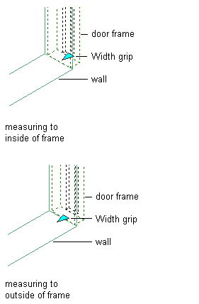
Measure to Specifies whether the width and height of the door is measured to the inside of the door frame or the outside. When a door is measured to the outside of the frame it is smaller by the amount that is deducted for the frame.

Illustration

Click the drop-down list and select Inside of Frame or Outside of Frame.
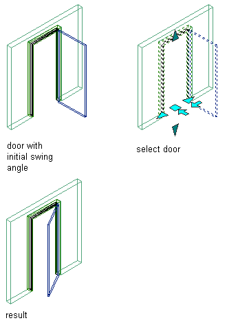
Swing Angle Lets you determine at which opening angle the door will be displayed.

Swing angle and display properties

The swing angle can also be determined in the display properties of the door style. The settings in the style override properties setting.

Illustration

Enter a value.
Location Category
Position along wallOnly during adding a door/anchored wallsSpecifies the insertion point of the door relative to the wall or door/window assembly. You have the following options:
  • Unconstrained: you can place the door anywhere on the wall.
    Note: This will work only if the Osnap is turned off, otherwise the door will snap to wall points.
  • Offset/Center: allows you either place the door in the center of the wall, or at a specified offset from the wall end.
Click the drop-down list and select Unconstrained or Offset/Center.
Automatic OffsetOnly during adding an anchored doorSpecifies the offset from the wall end during insertion if you have chosen Offset/Center for Position along wallEnter a value for Automatic Offset, or click  to pick points on the screen to specify the offset.
Vertical Alignmentanchored doors onlyLets you specify if the vertical height of the door should be measured to the door threshold or the door head.Click the drop-down list and select Threshold or Head.
Head Height/Threshold Heightanchored doors onlyDepending on the vertical alignment you chose, you can modify either the head height or the threshold height of the door. For example, if you want to create an elevated threshold, you select Threshold for Vertical Alignment, and then enter the elevation of the threshold under Threshold height.Enter a value for Head Height or Threshold height, or click to pick points on the screen to specify the height.
Anchoranchored doors only/not available for door toolsThe anchor worksheet lets you change the position and rotation of the door in relation to the wall it is anchored to.Click the Anchor worksheet, and enter the desired values there.
Additional Informationfreestanding doors only/not available for door toolsThe additional information worksheet lets you change the position of a a freestanding door relative to the WCS or UCS.Click the Additional Information worksheet, and enter the desired values there.
Endcaps Category
Opening Endcapanchored doors only/not available for door toolsLets you define an endcap style for the door where it is connected to the wall.Click the drop-down list, and select an endcap style. If you select By Wall Style, the wall endcaps will be used.