Friday, May 22, 2020

System Requirements For Civil 3D 2021


System Requirements For Civil 3D 2021
OPERATING SYSTEM
  • 64-bit Microsoft® Windows® 10
  • 64-bit Microsoft Windows 8.1
See Autodesk’s Product Support Lifecycle for support information.
PROCESSORMinimum: 2.5–2.9 GHz processor
Recommended: 3+ GHz processor
MEMORY16 GB
DISPLAY RESOLUTIONConventional Displays: 1920 x 1080 with True Color
High Resolution & 4K Displays: Resolutions up to 3840 x 2160 supported on Windows 10, 64 bit systems (with capable display card)
DISPLAY CARDMinimum: 1 GB GPU with 29 GB/s Bandwidth and DirectX 11 compliant
Recommended: 4 GB GPU with 106 GB/s Bandwidth and DirectX 11 compliant
DISK SPACE16 GB
POINTING DEVICEMS-Mouse compliant
FILE FORMAT CHANGESNo DWG or Civil 3D Object format changes¹.

¹Bridge and piping features added in 2021 may display as a proxy objects in prior versions.
.NET FRAMEWORK.NET Framework Version 4.8
 
Additional Requirements For Large Datasets, Point Clouds, And 3D Modeling
MEMORY16 GB RAM or more
DISK SPACE6 GB free hard disk available, not including installation requirements
DISPLAY CARD1920 x 1080 or greater True Color video display adapter; 128 MB VRAM or greater; Pixel Shader 3.0 or greater; Direct3D® capable workstation class graphics card.

Friday, January 24, 2020

Creating & Modifying Surfaces - Video Tutorial


To Record a Preview Animation

  1. Image result for To Record a Preview Animation 3d autocadIf the Animations panel is not displayed on the Visualize tab, right-click the Visualize tab and click Panels Animations.
  2. Start any navigation command such as 3DORBIT.
  3. Click Visualize tab Animations panel Animation Record.
  4. Navigate through the model to record the movement.
  5. When you are finished recording the animation, click Visualize tab Animations panel Animation Pause.
  6. To review the animation, click Visualize tab Animations panel Animation Play. In the Animation Preview dialog box, view the recording to verify that the animation is suitable for your presentation needs.
    Note:
    The playback of the animation gives you a general visual idea of the final output. It may not display the visual style or with the same quality of the final output.
  7. If you are satisfied with the animation, click the Pause button. Then click the Save button.
  8. In the Save As dialog box, choose a location and file name.
    Note:
    To change the file type, click the Animation Settings button. In the Animation Settings dialog box, Format option, click a file type. Click OK to return to the Save As dialog box.
  9. Click Save.

Creating Preview Animations


Image result for Creating Preview AnimationsYou can create 3D preview animations and adjust the settings before you create a motion path animation.
Preview animations are created with the controls on the Animation panel found on the ribbon and the 3D navigation tools. Once a 3D navigation tool is active, the controls on the Animation panel are enabled to start recording an animation.
The following commands can be used to create an animation
  • 3DCORBIT
  • 3DDISTANCE
  • 3DFLY
  • 3DFORBIT
  • 3DORBIT
  • 3DPAN
  • 3DSWIVEL
  • 3DWALK
  • 3DZOOM
To learn more about the 3D navigation tools available for creating an animation, see Use 3D Navigation Tools.

Survey Export Defaults

Use the Export Defaults to specify the properties for exporting survey data to a field book file.

Figure Export Conditions and Formats

When you select the Export Figures With Network property, the format of the figure data exported to the field book is dependent on the conditions of the survey data as shown in the following.
  • If the figure vertex has a point number, then the figure vertex is defined by referencing the point in the field book file:
    BEG <figure name>
    PT <point ID>
  • Then the following lines are added to the field book file:
    NE SS <point ID> <north> <east> <elevation> <description>
    BEG <figure name>
    PT <point ID>
  • Then the following line is added to the field book file defining the figure vertex:
    FIG NE <north> <east>
  • If the figure segment is a curve, then the curve segment is defined using the XC ZD (BULB) command. The BULB parameter is used when the delta angle for the curve is greater than 180 degrees.
  • If both ends of the curve segment reference point IDs, then the following format is output:
    XC ZD (AZ <point ID> <point ID>) (D <point ID> <point ID>)
  • Otherwise the following format is output:
    XC ZD <Azimuth> <Distance>

Point Export Conditions and Format

If you select the Export Point Identifiers property, for each figure vertex, the following formats are output to the field book file.
  • If the figure vertex has a point ID, then the following lines are added to the field book file:
    BEG <Figure name>
    PT <point ID>
  • If the vertex does not reference a point ID, then the following lines are added to the field book file:
    BEG <figure name>
    FIG NE <north> <east>
  • If Export Point Identifiers property is not selected, the following lines are added to the field book file:
    BEG <figure name>
    FIG NE <north> <east>
  • If the figure segment is a curve, then the curve segment is defined using the XC ZD (BULB) command. The BULB parameter is used when the delta angle for the curve is greater than 180 degrees.
  • If both ends of the curve segment reference point numbers (and if this check box is selected), then the following format is output:
    XC ZD (AZ <point ID> <point ID>) (D <point ID> <point ID>)
  • Otherwise the following format is output:
    XC ZD <azimuth> <distance>
When the Export Point Data is enabled, for each figure vertex that references a point ID, the following format is output to the field book file prior to the section defining the figures:
NE SS <point ID> <north> <east> <elevation> <description>

Editing Survey Figure Vertices

    Expand the Survey Figure Properties dialog box where you have editing options for each figure vertex displayed in the list view.
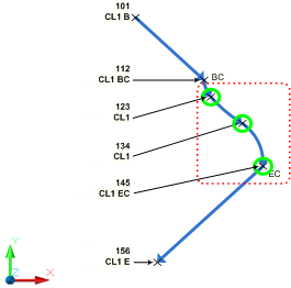
    You can add, remove, reorder, and change the point identifier (name or number) for each survey figure vertex. Figure preview graphics are displayed in the drawing indicating the selected vertices. An arrow head is displayed at the end of each segment to indicate the order (direction) of the figure vertices. Specify the color for the current vertex in the Interactive Graphics section of the Survey User Settings.
    The following illustration shows an example of the figure preview graphics:
    1. Open the Figure Properties dialog box by doing one of the following:
      • Right-click a figure in the drawing Edit Survey Figure Properties.
      • In the drawing select a figure. On the Figure contextual tab, click Survey Figure Properties
    • Find.
  1. Click to expand the dialog box.
  2. Use the icons to perform editing operations.
  3. In the list view Number or Name column, you can clear the value to disassociate the vertex from the referenced survey point. Enter a new point number or name if necessary. When the Number or Name column is clear, the Easting, Northing, and Elevation columns are enabled and you can edit those values.

To Redraw Adjusted Survey Figures

You can redraw all the defined figures in your survey database based on the current point coordinates.
After you adjust and update survey points, you can update the figures based on adjusted coordinates.
  • In Toolspace, on the Survey tab, do one of the following:
    • To update all figures, right-click the Figures collection Update Figures.
    • To update a single figure, click the Figures collection and in the list view, right- click the individual figure Update Figure.

An overview of pressure pipe networks

Pressure pipe networks are a collection of pipes, fittings, and appurtenances that make up a pressure system, such as a sanitary sewer force main or a water line. All of the parts are dynamic and link together to form a complete network of parts.
Select one of the pipes, and several grips appear, as well as a context-sensitive ribbon. The midpoint grip allows you to curve the pipe if it's not a ductile iron pipe, otherwise it will move the pipe. The context-sensitive ribbon contains tools specific to pressure pipe networks.
Select one of the fittings. Just like a pipe, it also has grips that you can use to edit it, and the context-sensitive ribbon shows you specific options for editing the fitting as well.
On the Toolspace, Prospector tab, expand Pressure Pipe Networks, and then expand Water. All the pressure pipes, fittings, and appurtenances for this drawing are listed here.
On the Settings tab of the Toolspace, expand Pressure Pipe Network, and here is a collection of Parts Lists. This is similar to the parts lists for gravity pipes in pipe networks; however, it contains parts that are specifically designed for pressure pipe networks only. Expand Parts Lists, and in this drawing are two Parts Lists: Water and Standard.
Pressure pipe networks also have three different catalogs to choose from. On theribbon, Home tab, expand the Create Design panel drop-down and select Set Pressure Pipe Network Catalog. In the Set Pressure Pipe Network Catalog dialog, under the Catalog Database File: drop-down, you can choose one of the three different catalog files to create a parts list from: Push on, Flange, and Mechanical parts. Not all part catalogs have the same part. Some contain PVC and HDPE, while another contains only ductile iron. PVC and HDPE are bendable, while ductile iron is not. There are valves only in some lists, while others contain crosses, reducers, caps and other fittings and appurtenances.
Always set the pressure network catalog before you begin creating your parts list for pressure pipe networks. It is recommended to create three parts lists, one for each catalog so you can swap between them as you design. Click Cancel to close the dialog.
Back on the Settings tab of the Toolspace, under Pressure Pipe Networks, right-click the Water parts list and select Edit. You can see that the Parts List has tabs for Pressure Pipes, Fittings, and Appurtenances. Select the Pressure Pipes tab and expand Water. In this tab, there is one type of family for your pressure pipes: ductile iron. Expand ductile iron, and there are several sizes available. Each pipe size has a style associated with it and a render material. To add parts, simply right-click Ductile Iron and select Edit Part Sizes. From here, you can add specific part sizes to your list beyond what you already see.
Similarly, when you select the Fittings tab and expand Water, there are three different types of fittings in the list. When you expand the different fittings types, there are several sizes available and each one has a style associated with it and a render material. Again, you can add sizes by selecting the fitting type, right-clicking, and selecting Add Part Size.
And lastly, select the Appurtenances tab and expand Water. There are two different types of valves in this list. When you expand the different appurtenances, you can see that there are several sizes available, and each one has a style associated with it and a render material. After reviewing the Parts List, click Cancel to close it.
In addition to the parts list, a pressure pipe network has an entire list of commands that you can control the defaults for.
On the Settings tab, there is also a collection for Pressure Pipes. Under Pressure Pipes are the Pressure Pipe Styles, which control the display of the pressure pipes, and the Label Styles for the pressure pipes.
Fittings also have Fitting Styles and Label Styles.
Appurtenances have Appurtenance Styles and Label Styles as well.
All of those settings can be configured and set up for the pressure pipes, fittings and appurtenances, so that when you start laying out your pressure pipe network, all the defaults are correct. You can then save all this information into a template file so that it is ready to be used each time you begin a new drawing.

How to display the cut length of Pressure Pipe

These are specified in the catalog. Open the Content Catalog Editor:
  • 2014: C:\Program Files\Autodesk\Autodesk AutoCAD Civil 3D 2014\Autodesk.Aec.Content.CatalogEditor.exe
  • 2015/2016: C:\Program Files\Autodesk\AutoCAD 201X\C3D\Autodesk.Aec.Content.CatalogEditor.exe
Cut_length
And to label in Civil3D:
Add the following:
<[Cut Length(Uft|P3|RN|AP|GC|UN|Sn|OF)]>
CutLengthLabel.PNG

How to manually transfer AutoCAD user settings

How to manually transfer AutoCAD settings from one computer to another when the specific AutoCAD version does not have the settings export/import utilities. This process can also be used to apply working settings to a specific user account, particularly if that account is unable to initialize AutoCAD due to a redirected profile folder or a similar environment being in place.
 Image result for How to manually transfer AutoCAD user settings

Solution:

User settings in AutoCAD for Windows are stored in two folders and a registry path (in AutoCAD for Mac, see the link referenced below). After installing AutoCAD and running the program once to make sure it works and has gone through its secondary installer process, follow the steps below to copy over the settings to another account or computer:
  1. Exit AutoCAD.
  2. Make a copy of the following two folders in a location accessible by all user accounts:
    For Windows Vista, 7, 8, and 10:
    C:\Users\<user>\AppData\Roaming\Autodesk\AutoCAD 20xx
    C:\Users\<user>\AppData\Local\Autodesk\AutoCAD 20xx
    For Windows XP:
    C:\Documents and Settings\<user>\Application Data\Autodesk\AutoCAD 20xx
    C:\Documents and Settings\<user>\Local Settings\Application Data\Autodesk\AutoCAD 20xx
    Note: These paths contain hidden folders.
  3. Export a copy of the AutoCAD registry key:
    1. Press WINDOWS-R on the keyboard to bring up the Run window, enter REGEDIT and click OK.
    2. Find the following registry key:

      HKEY_CURRENT_USER\Software\Autodesk\AutoCAD\Rxx.x\ACAD-xxxx:40x

      This path is unique for each version of AutoCAD. To see which 'ACAD-xxxx' refers to, select it and then look at the keys on the right side of the Registry Editor. One of the keys will show the install path to the AutoCAD it applies to. The '40x' number signifies the language version of AutoCAD.
    3. Right-click the 'ACAD-xxxx:40x' folder and choose Export.
    4. Enter a file name of your choice, choose a location to save the file, and then click Save.
    5. Close the Registry Editor.
  4. Log in to the destination user account.
  5. Copy over the two folders to their respective locations.
  6. Double-click the .reg file to apply it to the registry. The .reg file can be deleted after use unless you wish to use it again.
Additionally, some support files can be copied directly into the Support folder paths. Following is a generic list. Each product and version may have slightly different paths. Refer to the file paths in Options > Files for the version in question.

Plot Files
C:\Users\[USERNAME]\AppData\Roaming\Autodesk\AutoCAD 201XX\RXX\enu\Plotters
Plotters
C:\Users\[USERNAME]\AppData\Roaming\Autodesk\AutoCAD 20XX\RXX\enu\Plotters\PMP Files
Plot Styles
C:\Users\[USERNAME]\AppData\Roaming\Autodesk\AutoCAD 20XX\RXX\enu\Plotters\Plot Styles
Drawing Templates
C:\Users\[USERNAME]\AppData\Local\Autodesk\AutoCAD 20XX\RXX\enu\Template
Shapes
C:\Users\[USERNAME]\AppData\Roaming\Autodesk\AutoCAD 20XX\RXX\enu\Support


Warning!
Problems caused by improperly editing the Windows registry could render your computer operating system unusable. Microsoft provides a wealth of critical information that you need to know about the registry in the "Microsoft Knowledge Base". Use the Microsoft Registry Editor only at your own risk and only after backing up the registry as outlined for your operating system in the Microsoft article How to back up and restore the registry in Windows and in the related solution How to backup the system registry. Additional information about the registry is also contained in the Help topics in the Microsoft Registry Editor.

How to turn off the Start Tab in AutoCAD

Change the STARTMODE system variable.
  1. Type STARTMODE on the command line in AutoCAD.
  2. Enter 0 (zero) to turn off the Start tab or 1 to turn it on.
Turning it on requires restarting AutoCAD. If you are running AutoCAD in a single document mode (SDI =1), the Start tab will be displayed after you change the value of SDI to 0 and restart AutoCAD.

The Start tab in AutoCAD 2016 replaces the New Tab in AutoCAD 2015 and eliminates the NEWTAB and NEWTABMODE commands.