Digitizing Maps
Digitizing is the process of converting paper-based graphical information into a digital format. When you digitize a map, you use drawing commands to trace data from the paper map into a DWG file.
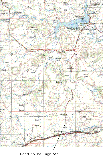
Digitizing lets you take information from raster images or paper maps, and enter it into a digital map.
Planning for Digitizing
Before you begin to digitize, consider the following:
- Suitability of source maps
- Global coordinate system
- Tiling maps
- Layer organization
- Data storage: internal or external
- Representation of node, network, and polygon topologies
If possible, plan on completing all digitizing for one map in one session because the map media may distort over time.
Digitizing Linear Objects
Linear objects are objects such as lines, arcs, and polylines.
- If you plan to use topography later to generate 3D views from digital terrain models, place linear objects at the elevations (Z- values) they represent.
- If you use the SKETCH command to trace an irregular line, make sure the variable SKETCHINC is set to a reasonable value, because each line segment ends at the interval set by SKETCHINC. The SKETCH command can create huge files for one small line when SKETCHINC is set to a small value.
- When digitizing irregular curves with PLINE or MAPDIGITIZE, the spacing of the selected vertex points should depend on the curvature of the line. Straighter segments require fewer points.

Examples of digitized curves - However accurately you work, you lose data when you digitize a curve. You need to digitize more points when you create sharp curves to ensure that the line is as accurate as possible; however, while you reduce the data loss, you increase file size and complexity. If you know the parameters used to define a regular curve, such as the radius or length, use the Arc option of the PLINE and MAPDIGITIZE commands for digitizing. Irregular lines, such as topography contours, should be continuous polylines. They can be smoothed with the Fit option of PEDIT if necessary. Set the PLINEGEN system variable to 1 (on) before digitizing, so that any dashed linetypes are evaluated correctly.
- When you finish digitizing a segment, mark it on the paper map so you do not repeat the digitizing. Double digitizing increases file size.
Digitizing Topology
When digitizing data that will be used to create a topology, follow these principles to achieve the most accurate results.
- Boundaries (or other polylines) should be completed with the Near, Intersection, or Endpoint object snaps to ensure that closed areas such as parcels, buildings, and water bodies are in fact complete polygons.
- Line segments should be snapped to existing end points where they intersect.
- When you are digitizing data for network topology, do not duplicate objects. For example, do not double-digitize boundary lines separating adjacent polygons. It's better to digitize adjacent polygons on the same layer with common lines defining common boundaries. If one edge serves two or more purposes, digitize the line once, then use the COPY and CHPROP commands to put a duplicate line on a different layer.
After you digitize the linear elements that form the basis of the topology, you should clean up any problems before you create the topology.
Digitizing Control Data Points and Monuments
When you are trying to match digitized maps with existing digital maps, you can use some known-to-be-accurate points common to both maps.
- Control Data Points — A system of geodetic control points covers the entire United States. The latitude and longitude, and often elevation, are established for these points. Similar systems exist for other countries, such as Bench Marks and Trigonometry Points throughout the United Kingdom.
- Monuments — If you are working with maps for a city or county, points used for establishing locations for all maps probably already exist: these points can include features such as public buildings, hill summits, and parts of highways.
When you are digitizing a map, use the following procedures to establish known control points:
- Create a layer called REFERENCE. On it, digitize at least four points corresponding to real-world coordinates such as the coordinate intersections of latitude and longitude lines. These points should either appear at the corners of your map sheet or surround the map features to be digitized. Be careful to note on the drawing the location of these reference points and their real-world coordinates. Use these points to register the map with the TABLET command, as described in To Register the Map.
- To ensure accuracy, you can also digitize other points such as control points and monument locations that have known positions. Digitizing more control points is important for To Match Map Edges or About Rubber Sheeting Two Maps operations.
Placing Annotation
While you are digitizing, you can add text to indicate nodes or important locations on a map. Use the STYLE command to define a text style that uses a simple font, such as isocp.shx, with a fixed text height so that you do not have to enter a text height each time you enter text. You can modify the text style and height when you finish digitizing.
Use the TEXT command to enter text as you digitize. Text should be single-line entries on the same layer as the feature it describes. If required, enter complex or lengthy text with the MTEXT command after you finish digitizing. For more information, look up "text" in the Help index.
Try to avoid overlaying the insertion point of the text and end points of the objects you are annotating.
posted by Feature and Technology @ June 07, 2019
0 Comments
![]()

0 Comments:
Post a Comment
Subscribe to Post Comments [Atom]
<< Home