Exercise 4: Editing Roundabout Components
In this exercise, you edit the geometry of the approach roads, move the roundabout center point, and delete roundabout components.
To edit approach road geometry
- Open Roundabout-Edit.dwg.
- Click tab
 Design panel
  Find.
Find. - Click tab
 panel
panel  Find.
Find. - Click the Approach_EW alignment.

- In the Create Roundabout - Approach Roads dialog box, under Approach Road Parameters, change the following parameters:
- Exit Radius: 25
- Entry Flare Length: 75
- At the bottom of the dialog box, click Next.
- In the Create Roundabout - Islands dialog box, under Construction Triangle Parameters, change the Length value to 75.
- At the bottom of the dialog box, click Next. Click Finish.The approach road is extended, the exit radius has increased, and linework for the islands and the pavement markings have been updated.

To edit roundabout location
- Click tab
 panel
panel  Find.
Find. - Click the Roundabout_ISLAND alignment.

- In the Create Roundabout - Circulatory Road dialog box, under Roundabout Center Point, click
 .
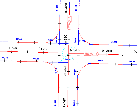
. - In the drawing, on the Road D alignment, click near station 0+130.Note:
Station 0+130 is not labeled, but the location is shown in the following image.
- At the bottom of the dialog box, click Next three times. Click Finish.The roundabout alignments and pavement markings are recreated around the new center point.

To delete roundabout components
- Click tab
 panel
panel  Find.
Find. - Click the Approach_SN (1) alignment.
 Both the approach road and the turn slip lane are deleted. The turn slip lane was deleted because its geometry was dependent upon the geometry of the approach roads to which it was attached.
 Note:
Note:
To delete the entire roundabout, click one of the circulatory road alignments while the Delete Roundabout command is active.


0 Comments:
Post a Comment
Subscribe to Post Comments [Atom]
<< Home